
Current to Alternative Directional Microphone Technologies III
Aart van Halteren, M.Sc., Chief Technical Officer, Sonion, The Netherlands.
Ann-Marie Sänger, Senior Product DevelopmentEngineer, Sonion, The Netherlands
In last week’s post a microphone module was introduced (M20) that combined superior directional equivalent input noise with a design that is very robust for temperature and humidity changes, as well as handling during hearing aid production. Without this robustness, directional microphone mismatch leads to poor hearing aid directionality.
This week’s post describes a newly developed directional technology that can tolerate even very severe mismatches between the applied microphones without significant degradation of directionality. This involves the use of two pressure gradient microphones (analogue directional microphones). Two possible implementations of this new technology developed by Sonion are described as follows:
- The UCUAC Microphone Module
- The U8UC Microphone Module
The UCUAC Microphone Module
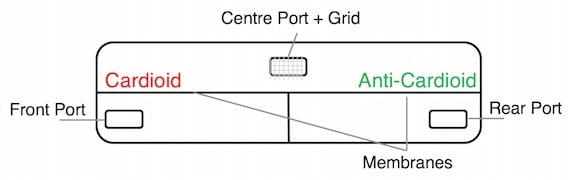
Figure 1. The UCUAC Microphone Module design.
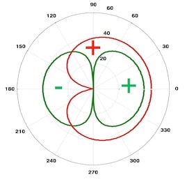
The UCUAC microphone module consists of two pressure gradient microphones picking up the pressure differences between three ports (Figure 1). One pressure gradient microphone has a cardioid polar pattern (UC); the other has an anti-cardioid polar pattern (UAC). Both cardioid and anti-cardioid delay are created by the same grid located in a shared center port. As a result, the polar patterns of both pressure gradient microphones are almost identical, but mirrored. In case of pollution of the center port grid, both pressure gradient microphones will still have identical acoustic delays.
The outputs of the pressure gradient microphones can be processed by simple weighted summation, as shown in Figure 2 for a target notch angle of 90 degrees.
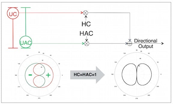
Figure 2. Processing of the UCUAC Microphone Module outputs.
The suggested processing of the UCUAC microphone module works also with polar patterns other than cardioid and anti-cardioid as long as they are mirrored. This is why pollution of the center port grid is not critical for the directional performance of the UCUAC module.
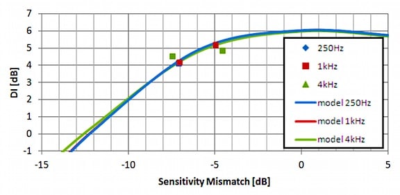
Figure 3. Result of Sensitivity mismatch on the DI (directivity index) for a UCUAC microphone module with 4.5 mm port spacing. The individual points (diamonds, squares, and triangles) represent prototype measurements.
As can be seen in figure 3, the UCUAC microphone module tolerates a mismatch of several dB between the applied pressure gradient microphones without showing significant DI (directivity index) degradation.
The U8UC Microphone Module
The U8UC microphone module consists of two pressure gradient microphones both picking up the pressure difference between a front and a rear port (Figure 4). One pressure gradient microphone has a dipole polar pattern (U8), and the other has a cardioid polar pattern (UC).
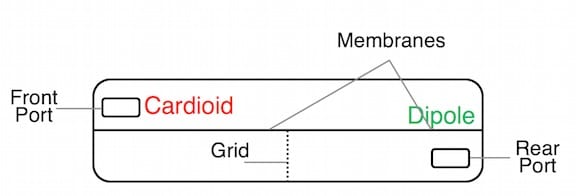
Figure 4. The U8UC Microphone Module design.
Again, the outputs of the pressure gradient microphones can be processed by simple weighted summation, as shown in Figure 5 for a target notch angle of 120 degrees.
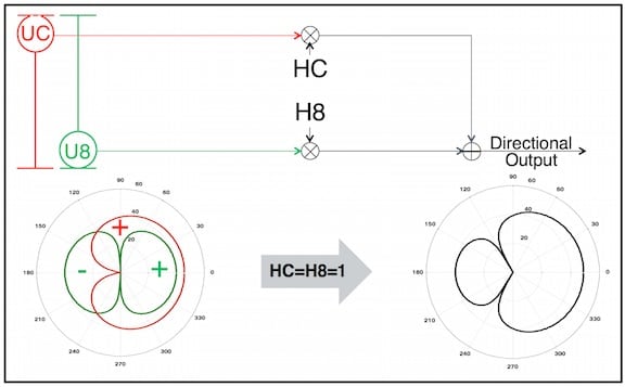
Figure 5. Processing of the U8UC Microphone Module outputs.
Figure 6 illustrates that even with a 3-dB sensitivity drift (which is VERY substantial) between the two pressure gradient microphones, the notch angle shifts by only ~10 degrees.
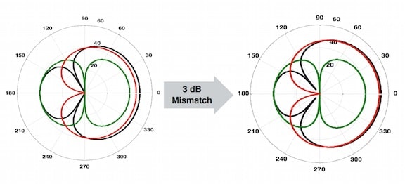
Figure 6: The result of 3 dB sensitivity drift on the notch angle.
Because the U8UC microphone module has two stable built-in notches at 90 and 180 degrees, the impact of mismatch on directionality is highest around 135 degree. This means that what is shown in figure 6 and 7 is close to a worst case scenario. For target notch angles close to 90/180 degrees the impact of mismatch is less.
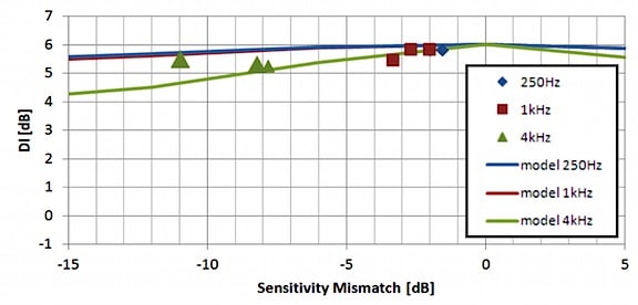
Figure 7. Result of Sensitivity mismatch on the DI (directivity index) for a U8UC microphone module with 4.5 mm port spacing. The individual points (diamonds, squares, and triangles) represent prototype measurements.
As recorded in figure 7, the U8UC microphone module tolerates a several-dB mismatch between the applied pressure gradient microphones without showing significant DI degradation.
Summary
This three-part series on new directional microphone developments has emphasized approaches to managing microphone mismatch, with the impact of improving robustness against microphone drift, which ruins hearing aid directionality.