

Ear impression material has been developed to provide certain characteristics to enable it to provide as accurate a representation of the concha and/or ear canal as possible. This means that it should flow properly, provide an accurate image of what it comes in contact with, set up properly without distortion, remove without distortion or breakage, maintain its shape during storing and/or shipping regardless of the temperature and humidity, and hold its shape over time.
For those practicing in the hearing aid discipline and in auditory rehabilitation, it is helpful to understand some of the ear impression terminology that describes the physical properties of ear impression and other soft ear product materials. The intent here is not to go into detail of the different descriptive terms, but to provide a working understanding of ear impression material terminology.
Impression Materials can be Considered Generally as Follows:
- Rigid
- Plaster of Paris (Impression Plaster)
- Impression compound
- Zinc-Oxide Eugenol plaster
- Impression waxes
- Elastic Hydrocolloid – Hydrocolloids are further classed as reversible or irreversible.
- Reversible – Agar
- Irreversible – Alginate
- Elastomeric – Examples of elastomeric impression materials include elastomers, polysulfides, polyethers, additional silicone, and condensation silicone. Of these three categories, it is the elastomers that are currently used.
Note: The required type of material for taking an impression and the anatomical area that it is intended to cover will depend on the clinical application.
Two types of impression materials have been used most commonly for taking ear impressions:
- Ethyl methacrylate (traditional material, acrylic material, or liquid and powder. This material was used for at least 30 years, but has been replaced with silicone impression material.
- Silicone – this is today’s standard material for taking ear impressions. But,
- Not all silicone is the same. Or, as a silicone chemist once told me, “Silicone is silicone is not silicone.”
- Silicones are made up of different formulations. How they perform depends on the silicone purity (how much “filler” material replaces pure silicone), and the intended purpose. Less expensive silicone tends to have more “filler.”
Impression Materials Differ in Their Physical Properties
Ear impression materials do not all share the same properties and qualities. They can vary considerably, and the following terms are used to describe these properties. The terminology may also describe some of the elastomeric properties used for soft hearing aid housings and/or earmolds/ear tips. While many different measurements can be used to describe the properties of ear impression material, this post will discuss primarily those terms that are used in ear impression lingo. Many other terms are used primarily by engineers and chemists developing various elastomeric products. For those practicing in the hearing aid discipline, it is good to understand some of the terms used that describe the physical properties of ear impression and other soft ear product materials. The terms to be discussed are:
- Viscosity
- Hardness
- Tensile (stretch) properties
- Ultimate tensile strength (UTS)
- Tear strength
- Elongation
- Compression set
- Type of cure (addition or condensation)
- Contraction ratio (shrinkage?)
- Polymerization
- Thixotropy
Viscosity
Viscosity is resistance to flow. This refers to the internal property of a fluid that affects the speed at which a fluid flows. A low viscosity material is very runny (water is a good example). A high viscosity material moves slowly (think of honey). So, viscosity is a measure of how easily a fluid can flow.
Silicone ear impression material is considered a fluid, but all ear impression material does not share the same viscosity. This is especially true of those impression materials administered using a gun for injection. Their viscosity has to be lower because of at least two reasons: (1) the material has to mix and pass through a narrow diameter mixing cannula, and (2) it has to flow fairly easily without undue pressure by the person administering the impression material into the ear. For those impression materials that are not gun administered (syringe or hand packing methods), viscosity is higher because the mixing is generally done in the hand.
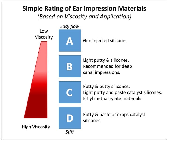
Figure 1. Simplified scale used to identify the general viscosity of ear impression material. C and D have been considered standard and have been used to take ear impressions for decades; ethyl methacrylate from the 1940s, and silicones from the 1960s. A and B were developed in the 1990s for deeper impressions for peritympanic and CIC (completely-in-canal) hearing aids2. (Modified from Pirzanski1).
Viscosity, as it relates to ear impression material, is a measure of the consistency of the material before the chemical reaction of polymerization. Most manufacturers do not describe the viscosity, and it varies from one manufacturer to another. One has to be careful in this discussion because there is not necessarily a relationship between the viscosity and the end Shore hardness of the material following polymerization. In other words, a very viscous impression material can still have a high cured hardness. This depends on how the developer combines the polymers and monomers. Because the viscosity is not identified on ear impression material, it may be somewhat helpful to utilize a rough scale suggested by Pirzanski1 (Figure 1.)
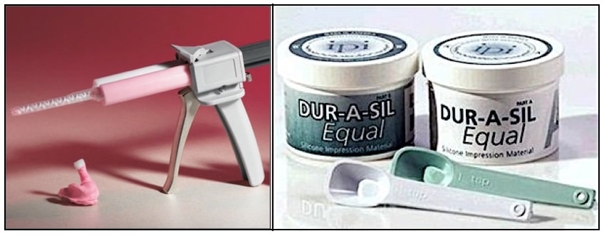
Figure 2. Viscosity comparisons of two forms of impression material administration. For deeper ear impressions or those administered using a gun, the viscosity is lower (left image), but higher for those requiring hand mixing (right image).
Viscosity is determined by its internal resistance or friction and is measured/compared using an instrument called a viscometer, of which there are several types. The thicker its contents, the higher is its viscosity (Figure 2). It is also affected by temperature. For liquids, viscosity decreases as a fluid is heated, and viscosity increases as the fluid is cooled. This is an indirect relationship.
Shore Durometer (Hardness)
The hardness or softness of the material often determines what is used for taking ear impressions. It should be mentioned that Shore durometer is a measurement of the hardness following polymerization, or after the ear impression material has set. Shore does not define the flow characteristics of the material before hardening, so it can’t be used to estimate the material after mix consistency. But, the lower the value, the softer the finished impression.
Durometer Testing of Hardness – The most common instrument for measuring rubber hardness as it applies to ear impression material is the type A durometer. In this device, a spring pushes a metal indenter of a specified size and shape into the material surface, and measures how far it penetrates. This is not a test of piercing the material, but to see how far the indenter penetrates under the test conditions. The softer the specimen, the farther the indenter will penetrate. A common way to express the hardness scale is Shore, such as Shore A. Figure 3 shows the comparison between a 20 Shore A versus a 90 Shore A durometer measurement3. The Shore A indenter deflects 0.001 inch for each durometer point. The term durometer is often used to refer to the measurement as well as the instrument itself.
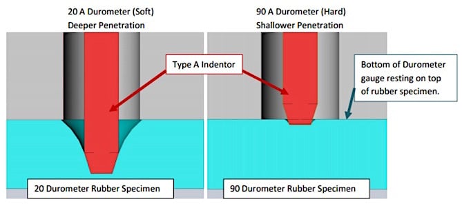
Figure 3. Type A durometer hardness test showing the difference the indentation device penetrates for soft and hard materials. The specimen is flat, parallel, and of a certain minimum thickness. ASTM (American Society for Testing and Materials) and ISO (International Standards Organization) each specify different minimum thicknesses (ASTM D-2240 ~6.1 mm, and ISO 4 mm. (Photo from Tranquilli, 20143).
Results obtained from a durometer test are a useful measure of relative resistance to indentation. However, the Shore durometer hardness does not serve well as a predictor of other properties, such as tensile properties (break, strength, elongation). Additional tests are required to provide this information.
The term Shore comes from Albert Shore, founder of the Shore Instrument Company and the man who originally defined the scales. Any specification may be referred to as either a Shore or Type — for example, “Shore A 70 durometer” or “Type A 70 durometer3.”
Hardness is often confused with flexibility. Although both properties reflect how a product feels in the customer’s hands, one is a measurement of the resistance to bending, while hardness measures the resistance to indentation. However, there is somewhat of a relationship with certain elastomer families – generally, as hardness goes up in value, so it also has less flexibility4.
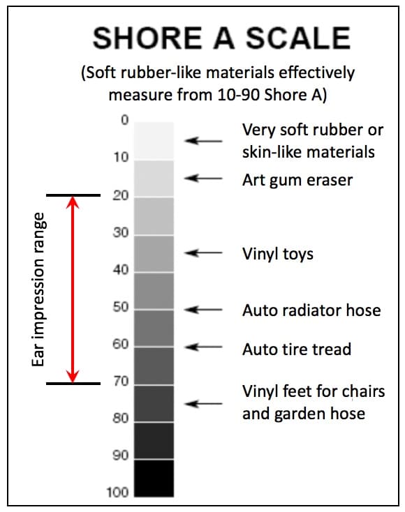
Figure 4. Examples of different rubbers on a Shore A scale. Ear impression material has ranged from 20 to 70 Shore A.
Of course, the sample thickness plays a role in the elastomer hardness measurement. It is assumed that ear impression suppliers/manufacturers have provided their Shore readings in compliance with the Standard. Also, the ASTM D2240 Standard recognizes twelve different durometer scales using combinations of specific spring forces and indenter configurations for other than soft materials. They will not be discussed here. Examples of the hardness of different materials is shown in Figure 4.
Tensile (Stretch) Properties
Tensile properties are measurements used to describe how an elastomer reacts to forces applied in tension. Silicone ear impression material is an elastomer, and as such, is subject to form changes. Some of the tensile measurements that are important relative to elastomers, and therefore also to ear impression materials, are described as follows4:
- Tensile at break – This measures how much force is required for a stretched piece of elastomer to break. The unit of measurement is typically given in pounds per square inch (psi) or megaPascals (MPa). This is called Ultimate Tensile Strength (UTS). Ear impression material, following polymerization and during removal from the ear canal, stretches somewhat from friction as it pulls past the turns of the ear canal. It is important that it not break during this process and leave portions of the impression in the ear canal.
Tensile strength can be defined as the maximum amount of tensile stress that an object can take before breaking apart, and is tested by performing a tensile test. This test records the amount of stress an object undergoes while external forces are acting upon it (Figure 5).
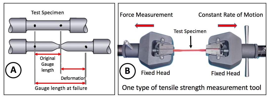
Figure 5. A test specimen (A) in its normal state, and showing the length at its failure (breakage). The right side (B) shows one type of tensile strength measurement tool/machine for making such a measurement.
- Tear strength – This describes how well the elastomer resists tearing. The test is made essentially the same as tensile break, except that the test bar (impression material) is notched on one side to provide a propagation point (Figure 6). The material is stretched and the amount of force at which it tears completely is recorded. The unit of measurement is typically psi or kiloNewtons per meter (kN/m).
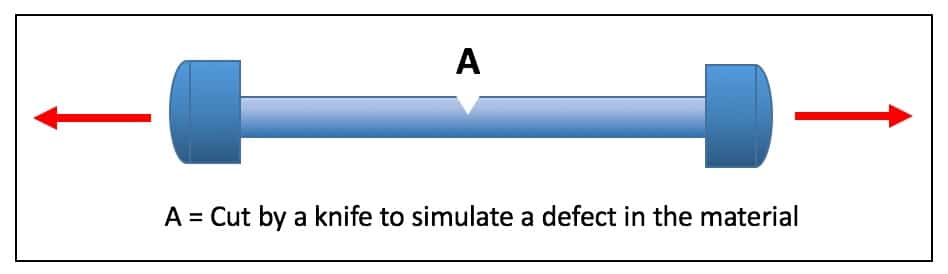
Figure 6. Resistance test to tear at maximal elongation (incipient fracture), measured using a tensile machine, such as in Figure 5.
The following example demonstrates how such a test was performed to demonstrate the resistance to breakage of elastomeric materials used for hearing aids. The example applies to the original soft shell Full Comfort™ material of the Philips XP Peritympanic hearing aid5. The standard soft shell material tore after an elongation of 70%, as opposed to 270% for the Full Comfort™ sample. The samples were then cut with a knife to simulate a structural defect in the materials (A, in Figure 5). While the original material tore immediately upon elongation, the Full Comfort™ material reached the 270% elongation before it tore.
- Elongation at break – This does not measure how hard or easy the material is to stretch, but simple measures how far it will stretch before it breaks. A soft elastomeric material will typically have a much higher value than a hard rigid material.
This post will continue next week, discussing some of the terminology describing elastomers, such as used for ear impressions.
References
- Pirzanski, C. (1999). Anatomically accurate ear impressions. Audecibel, p.11.
- Temeer, P. (1994). Ear canal expansion using different ear impression materials. Unpublished report. Eindhoven, The Netherlands: Philips Hearing Instruments.
- Tranquilli, J. Hard to handle: measuring durometer Shore. Apple Rubber Products, Inc. (2014).
- Thermoplastic Elastomer (TPE) FAQS. (2016).
- Staab, W. The Philips XP peritympanic hearing aid. (1996). Seminars in Hearing, Vol 17, No. 1, pp. 33-48.
Feature image from quora