
A previous post opened a conversation about 3D printing. This technology is currently being used in the hearing aid industry, as it is in many other industries, for modeling, and even for some product fabricating, especially earmolds and custom-molded shells for in-ear products.
Four different types of 3D printing processes likely to be encountered, are:
- Stereolithography (SLA)
- Selective Laser Sintering (SLS)
- Fused Deposition Modeling (FDM)
- Multi-Jet Modeling (MJM)
Stereolithography (SLA)
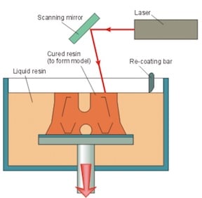
This 3D printing process is generally considered the pioneer of all other 3D printing processes. It was introduced and patented in 1988 by Charles W. Hull, the founder of 3D Systems. This process makes use of a vat of liquid photopolymer resin that is cured by a UV laser (Figure 1, and described previously). The laser solidifies the resin layer by layer, creating the entire object.
The SLA printer consists of four main parts:
- A printer filled with a liquid plastic (resin)
- A perforated platform that is able to move down and up
- A UV laser
- A computer to control both the laser tracings and the platform
As described in a previous post, in the SLA process, a thin layer of plastic (often between 0.05 and 0.15 mm) is exposed above the platform. Into this thin layer of plastic (resin), the laser “draws” the pattern of that slice of the object as depicted in the design files from the computer. The touch of the laser onto the resin hardens it relative to the path of the laser. Then, a new layer of resin flows over the hardened resin as the platform is lowered slightly. This process continues, layer-by-layer until the entire object has been constructed. The resultant object is generally smooth. Because of the nature of the SL process, it requires support structures for some parts, specifically those with overhangs or undercuts. These support structures are designed into the CAD file and are removed manually when the product is complete. The quality of the object depends on how complex the SLA machine is.

Figure 1. Stereolithography employs an ultra-violet laser beam to cure liquid photo polymer in layers. A platform starts one layer depth below the surface of the polymer material and the laser cures the first layer based on thin data slices of the object from a computer. The platform is lowered by one-layer depth and the next layer is cured. The process is repeated until the object is completed.
Selective Laser Sintering (SLS)
One of the most commonly used 3D printing techniques is that of Selective Laser Sintering (SLS). In this process, tiny particles of ceramic, glass, or plastic are fused together by the heat of a high-power laser to form 3D objects. Like all other 3D printing processes, it starts with designing of a 3D model using CAD software. The files are then converted to an appropriate format recognized by the 3D printer.
Instead of a liquid resin tank, as used in SLA, SLS uses powder materials, usually plastics like nylon, to print the 3D objects. The computer controlled laser is instructed to print the appropriate object by tracing a cross-section of the object onto the raw material (powder). The heat from the laser is equal to, or slightly below, the boiling point of the particles. As in all prototyping processes, the parts are built upon a platform that adjusts in height equal to the thickness of the layer being built.
As soon as the initial layer of the object is formed, the platform of the 3D printer drops by no more than 0.1mm (example) and a new layer of the powder is placed over the previous layer. This layer is then exposed to the laser to harden the material in that layer. Additional powder is deposited by rolling it onto the platform on top of each solidified lay and sintered. This process continues layer-by-layer until the object is created. The powder is maintained at an elevated temperature so that it fuses easily when exposed to the laser. The finished product must then be allowed to cool before being removed from the printer. Figure 2 shows the process, and a video showing the process at this link.
SLS uses a moving laser beam to trace and selectively sinter powdered polymer and/or metal composite materials into successive cross-sections of a three-dimensional part. Unlike SLA, special support structures are not required because the excess powder in each layer acts as a support to the part being built.
Selective Laser Sintering (SLS) was developed and patented (1989) at the University of Texas in Austin, by Carl Deckard, an undergraduate student, along with his professor, Joe Beaman. The process was acquired by 3D Systems in 2001.

Figure 2. A CAD file that has the data of thin slices of an object to be fabricated is passed through a laser and draws the image of that slice into the powder, where it hardens as drawn by the laser. That layer is then dropped slightly, and the leveling roller pushes another layer of powder over that image. This new layer is again exposed to the heat of the laser with the image of the next slice from the CAD program, and this layer is then formed. This layering process continues until the object is completed.
A following post will describe Fused Deposition Modeling (FDM) and Multi-Jet Modeling (MJM) 3D printing.