Check and Double Check – Open Tube, Part 2
Dilemma – Gain vs. Acoustic Feedback

Mead Killion (center), Don Wilson (left) and Jonathan Stewart (right). All three engineers have been at Etymotic the entire 30 years!
A previous posting presented a hearing aid fitting dilemma – one that is not generally discussed. One side presented information on a closed fit RIC showing that as the insertion depth increased, so did the high-frequency amplification – an expected advantage based on Boyle’s Law (Staab). The other side however, showed that with a deeper insertion of an open fit (tubing), this led to less gain before acoustic feedback – a disadvantage (Killion and Wilson).
Because the topic was concerned about data accuracy and the need for rechecking results, the two sides decided to recheck what each had found and to report the results in a future posting (this two-part series). This posting reports on the data from Killion and his colleagues at Etymotic Research, and that from Staab was presented in last week’s posting.
Killion, Wilson, and Stewart Feedback Recheck
Measurement Setup Details
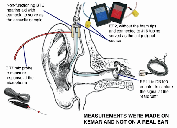
Measurements were made on KEMAR wearing a conventional BTE, but for acoustic accuracy only. The logarithmic chirp signal was actually delivered using an ER2 at the position of the earhook connection of the BTE hearing aid. Instead of the ER2 standard front tube (minus the yellow foam), an equivalent continuous length of #16 tubing with a gentle bend to allow easier positioning and to mimic a BTE’s earhook and tubing (Figure 1) was used to deliver the signal. The ER2 provided a wide bandwidth (16 kHz bandwidth) to provide a flat-response microphone to the KEMAR manikin.
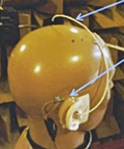
The pressure at the “ear drum” was captured with an ER11 (Etymotic Research Inc. 1/2” microphone) in a Knowles Zwislocki DB100 ear simulator, and the pressure at the BTE microphone position was captured with an ER7C probe mic. Testing was performed in an anechoic chamber (Figure 2). The stimuli and responses were generated and captured by SysID as a 4096pt FFT.
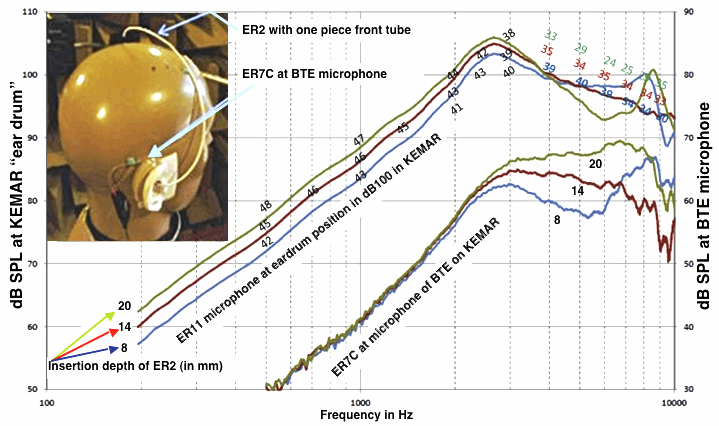
The original intent was to make these measurements from two sizes of “ears” on KEMAR for the right and left ears separately. However, after performing a few sets of measurements, results were similar and, consequently, were averaged together to derive the six measurements for each curve shown in Figure 3.
Result: Greater Feedback With Deeper Earpiece Insertion
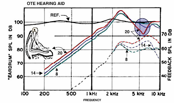
Figures 3 and 4 illustrate the initial and follow-up measurements respectively of the Killion and Wilson data. The results are similar, although the pressure shown with the 8-mm insertion (Figure 4) did not behave like the previous data above 5000 Hz (Figure 3).

Figure 3. Results (Figure 8) of Killion and Wilson data, Response-modifying earhooks for special fitting problems, Audecibel, Fall, 1985.

Figure 4. Re-measure of Figure 8 of Killion and Wilson (1985), on KEMAR wearing a BTE (for placement acoustics only) in an anechoic chamber with an ER11 microphone in a Knowles DB100 Zwislocki ear simulator coupler and ER7C probe microphone. A flat logarithmic chirp signal was delivered using the ER2. The numbers represent the gains available before feedback for the different insertion depths (pressure at the BTE microphone subtracted from the “ear drum” pressure).
It is possible that this difference could be a result of the acoustically-placed BTE hearing aid used, which was not representative of that measured in the 1985 study. Might the results be improved if the hearing aid could be duplicated? Unfortunately, the BTE hearing aid assortment currently available in the measurement lab has not shown much effect on the results. Still, the conclusion that the shallow insertion is less susceptible to acoustic feedback is supported by this repeat study. Assuming a worst phase case of interfering signals, the maximum gain before feedback in the 3-6 kHz region is 15 dB less with a deep insertion than with the shallow insertion, which was essentially what Killion and Wilson found in 1985.
Summary
That the shallow insertion is less susceptible to acoustic feedback for a tube-fit confirms the Killion and Wilson 1985 study and is supported by this repeat study.


Wayne (and Mead)
Thank you for a very interesting discussion.
David