
Last week’s blog provided basic anatomical background related to the tympanic membrane (TM). The intent of this week’s blog is to take the anatomical information related to the TM from last week, combine it with some additional information, and then show how the TM, working behind the scenes, influences the clinical hearing aid practice. Originally scheduled for two parts, a third part is scheduled for next week’s blog.
Ear Canal Composition
The ear canal consists of cartilaginous and bony sections. The cartilaginous section accommodates to and tolerates virtually everything placed in it within reason. This is because the underlying tissue is approximately 0.5 to 1 mm in thickness, and has a well-defined subcutaneous layer (Figures 8 and 9). Considerable expansion is tolerated, meaning that the impression does not have to be “accurate,” which is a definite advantage–one that has saved many a dispenser’s “bacon” when attempting to fit a hearing aid coupling device to the ear.
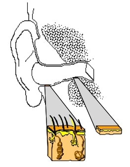
Figure 8. Artistic rendering showing the difference between the skin and underlying structure of the cartilaginous outer section of the ear canal versus that of the bony section.
The bony section, which is closer to the TM, has essentially no forgiveness and has difficulty accepting even soft materials. The underlying tissue is about 0.1 mm in thickness, and there is essentially no subcutaneous layer, and that which exists, is highly vascular. Little or no variation exists, meaning that even a tight impression block would result in no enlargement of the canal in this area. And, the closer to the TM, the less variation in the canal wall can occur.
Figure 9. Skin thickness and subcutaneous layer of the cartilaginous ear canal.
Visualization of the TM
How can one visualize the TM? Routinely, the TM can be visualized easily with the use of a handheld or video otoscope (Figure 10).
Figure 10. Right tympanic membrane.
However, such approaches ignore an important feature in that they are one-dimensional, and as such, do not show depth. In the photo of Figure 10, it is not possible to tell that the upper portion of the eardrum is closer to the eye than is the lower part by approximately 5 mm. 3D imaging techniques recently introduced for “taking” ear canal dimensions, would seem to offer application for providing better “visualization,” but placing the current 3D probes against the TM is not advisable. Additionally, they would have to be modified so that the scanner light would have a forward-facing scanning element rather than rotating around the core as currently available.
What Does the TM Look Like With Its Angles?
The series of photographs that follows shows ear impressions that include the TM taken by the author on living individuals. Special techniques, materials, and care were used in taking these impressions for the first real deep canal hearing aid fitting, the Philips XP Peritympanic hearing aid {{4}}[[4]] Staab, W.J. Deep canal length hearing aid fittings – a rationale and procedures, Hearing Instruments, Vol. 42, No. 1, January 1991[[4]].
The three ear impressions in Figure 11 clearly show the TM, including the cartilaginous annular ring that surrounds the tympanic membrane. The depth (shown in reverse) of the umbo varies, but in each case, the angle of the TM approximates 45 degrees. (This is not as easily seen on the leftmost ear impression because it is not held at the proper angle).
Figure 11. Three ear impressions of the complete ear canal, prominently showing the tympanic membranes and their 45 degree angles, along with a clear view of the annulus.
The ear impression in Figure 12 shows a very tortuous ear canal, but the TM and “bump” of the concave umbo (shown here as being convex) is clearly visualized – again with the TM at approximately a 45-degree angle.
Figure 12. A very tortuous ear canal – uneven and severe bends that make this a difficult ear from which to take an impression. Still, the landmarks of the TM and umbo are easily seen.
Figure 13 shows two additional ear impressions with the intent to show that focusing on the TMs only, the TM length is about 5 to 7 mm.
Figure 13. Two very different ear canals. That on the left has an unusually long area following the second bend, and is close to 30 mm in total length. That on the right would essentially have the block touching the TM when placed beyond the second bend. The total length of this ear canal is closer to 20 mm at its longest dimension.
Practical Fitting Implications
At least two immediate implications arise as the result of understanding better the anatomy of the TM and how it relates to the ear canal. The first implication relates to the taking of ear impressions, and the second relates to fitting hearing aids more deeply into the auditory canal – a current trend that is likely to continue to grow.
Additional complete ear canal impressions that include the imprint of the TM are shown in Figures 14 through 17. As an observation only, it appears that longer ear canals seem to not have as many unusual and sharp curves, or not as many variations in diameter – not as tortuous.
Figure 14. Complete ear canal with imprint of tympanic membrane.
Figure 16. Complete ear canal with imprint of tympanic membrane.
Figure 15. Complete ear canal with imprint of tympanic membrane.
Figure 17. Complete ear canal with imprint of tympanic membrane.
Next week’s blog will close out this discussion on the influence the tympanic membrane has on taking ear impressions and on hearing aid fittings.