
Hearing light – Demonstrations of auditory sensitivity, Part II

Dr. Manfred Euler
This is a continuation of “Can You Hear Light?” from last week’s post by Dr. Manfred Euler, Leibniz-Institute for Science and Mathematics Education (IPN), Kiel.
Signal amplification via resonance
The amplification process is based on the resonance of the air-filled cavity equipped with an opening to emit sound. Such a device is called Helmholtz resonator. If the air is suitably excited, the system oscillates with its resonance frequency, which depends on the dimensions of the cavity and the opening. The acoustic oscillations are analogous to a mechanical mass-spring system (Figure 3). The compressible air inside the cavity acts as an elastic spring, while air in the opening represents the oscillating mass. Starting from this mechano-acoustical analogy, one can calculate the resonance frequency.
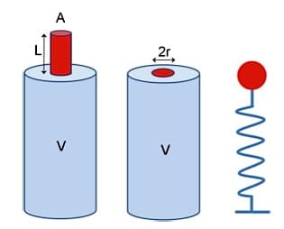
Figure 3. Two versions of Helmholtz resonators. a – Bottle-type with cylindrical neck; b – Pickle-jar type with circular opening; c – equivalent mechanical oscillator model (mass-spring-system).
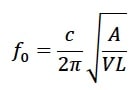 The resonance frequency f0 of a resonator with a cylindrical opening is approximated by the formula:
With c-sound velocity, A-cross section area, L-effective length of tube{{1}}[[1]] https://en.m.wikipedia.org/wiki/Helmholtz_resonance[[1]].
This formula applies to bottles with a straight neck. The pickle-jar converter lacks the cylindrical neck. The effective length of the oscillating air “plug” inside the circular opening is in the order of the radius (≈ 1.5 r). The resulting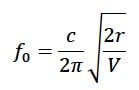 resonance frequency of that system is approximately:
There is a maximum response if the periodical driving frequency matches the resonance frequency. In order to tune the system to the desired frequency, the radius r and the volume V have to be adjusted in advance. However, there is a more refined version of the experiments with an elegant way of tuning the system continuously during operation.
Hearing light with a tunable resonator
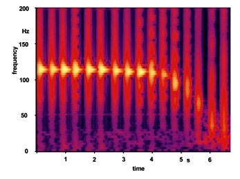
Figure 4. Short-time spectrograms of a sequence of bottle-tapping sounds. During the measurement the bottle approaches the pinna until close mechanical contact at about 6 seconds.
The idea arose when testing various wine bottles to find suitable resonators. The resonance was checked by listening to the sounds from tapping the bottle with a finger{{2}}[[2]]Euler, M. Hands-on resonance-enhanced photoacoustic detection. The Physics Teacher 39, 406 (2001); doi: 10.1119/1.1416310[[2]]. The tapping sound gets lower when the bottle’s mouth is approached closely to the ear. This observation provided the clue to create a simple hands-on tunable photoacoustic resonator.
Figure 4 shows the downward tuning effect. The bottle with a microphone inside was tapped regularly with the finger while the opening was moved towards the ear canal. The spectrograms of typical straight neck wine bottles show a substantial decrease of the resonance frequency from 115 Hz to about 50 Hz. The frequency shift depends on changing the boundaries of the resonating system when it approaches the outer ear. A similar mechanism is used by horn players, who fine-tune their instruments manually by ‘stuffing’, i.e., by inserting their hand into the horn opening.
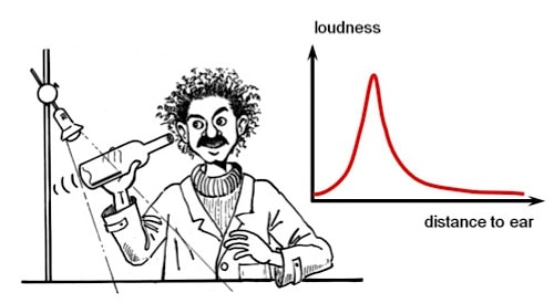
Figure 5. Amplification of the photoacoustic signal by manually tuning the wine bottle resonance.
Based on these findings, the design of a tunable resonance-enhanced detector system is nearly self-explanatory. Take a 750-ml wine bottle with a straight neck. The glass should be clear, not colored. Insert an aluminum foil covered with a soot layer and shine light from an ac-powered incandescent bulb on the black surface. Move your head in order to approach the bottle with your ear. You should be able to hear a hum. At first, the signal will get louder during approach, but it will begin to fade below an optimum distance of approximately 0.5 cm. The experiment allows you to create and observe a tuning curve in a hands-on and ears-on way as Figure 5 shows schematically.
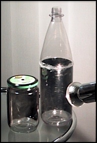
Figure 6. Two different home-made photoacoustic resonators.
At maximum loudness the receiver is tuned to the photoacoustic signal. The whole system comprising the bottle volume and the air gap between the mouth and the outer ear of the experimenter oscillates in resonance. The experiment makes the observer part of the observed system and provides a bodily experience of resonant tuning to selectively amplify weak sound signals. The manual tuning of the acoustic system is fully analogous to adjusting the electronic resonance circuits of old day’s analogue radio receivers in order to select a specific station.
An additional remark for the 60-Hz AC community is necessary. Unfortunately, the standard 750-ml wine bottles first have to be tuned upwards to amplify a 120-Hz signal by lowering their volume. As an alternative, suitable resonators can be created from clear plastic bottles (Figure 6). Cut the bottle into two pieces, attach the soot-covered sheet to the wall, and reassemble the bottle with a tight glue layer to prevent acoustic leaks. Adjust (if necessary) the volume or the neck area according to the formula mentioned earlier in this post to set the resonance frequency above 120 Hz. Using large-volume plastic bottles improves the audibility of the photoacoustic signal considerably. The converter area and the quality of the resonator are increased, giving rise to a higher signal power and a better signal-to-noise ratio. This allows even persons with moderate hearing problems to detect the signal.
A smart sensor system
The hearing light experiments demonstrate the sensitivity of our ears and the role of resonance to amplify and to discriminate weak signals in the presence of noise. Hopefully, the project will stimulate further activities to learn more about the intriguing mechanisms that underlie the complex functions of the human auditory system. The experiments also point out the role of temporal effects in auditory signal processing. While our optic system is too slow to resolve the periodic flickering of AC-powered electric lighting, our ears can perceive the intensity fluctuations as a low-frequency tone. The neural system is able to transmit and process oscillatory signals below 1 kHz in real time. The temporal processing scheme is called periodicity principle. It encodes pitch as a neural timing effect. Periodicity pitch is relevant for the perception of fundamental frequencies in speech and music.
In the analysis of sounds, a second complementary signal processing scheme is involved, the so called place principle. The perceived pitch depends on which place in the inner ear is set into vibration. The inner ear carries out a mechanical spectrum analysis, based on the traveling wave mechanism. It systematically maps the specific frequency components of a signal to different positions along a sensory surface, the basilar membrane. Additionally, there is an active neuro-mechanical feedback process involved that amplifies the oscillations by feeding in energy. It enhances the sensitivity, increases the dynamical range, and creates sharp tuning. The active processing mechanism is smart because it can adapt the amplification to the incoming signal. In this model, the inner ear corresponds to a set of coupled active resonators that automatically tune to the signal in a self-organized way. The active oscillations go along with essential nonlinearities. A forthcoming contribution will present model experiments with active oscillators to investigate the inherent peculiarities of active processing.