
 Hearing Aid Coupling
From an historical point of view, the history of coupling a hearing aid processor to deliver sound to the ear might be ordered as follows: (1) stock ear coupling, (2) custom earmolds, (3) imaging, and (4) same-session coupling.
The purpose of an earmold/earpiece is to direct sound to the tympanic membrane without feedback; it should fit the ear comfortably and cosmetically, provide stability of the hearing aid to the ear, and sometimes provide for acoustical advantages to enhance hearing aid performance and user acceptance.
This is the last in this series of a ride through the history of hearing aid evolution.
The earpiece is often the harbinger of unsuccessful hearing aid use because of its intertwined relationship to acoustic feedback, the occlusion effect, discomfort, cosmetic concerns, remakes, patient listening downtime, cost, etc. The earpiece plays a major role in issues related to the problems or success of wearing hearing aids.
Stock Ear Coupling
Prior to customization of earpieces, different configurations, sizes, and materials of “stock” earpieces were used to connect the hearing aid to the ear with varying degrees of success, but mostly poor (Figure 1). It would be an error to indicate that “stock” earpieces no longer are used, because many of the current RIC and RIA hearing instruments are fitted using flexible eartips of varying sizes and configurations from an existing supply of pre-sized and available couplers. This will be revisited later in this post.
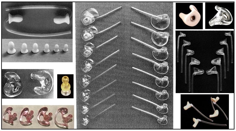
Figure 1. A sampling of stock hearing aid coupling devices to the ear. These ordinarily are available in a same configuration, but in a variety of sizes to fit different size ears.
Custom Earmolds/Earpieces
Custom earpieces used to fit hearing aids made their appearance in the mid-1950s and continue as a standard fitting approach. Custom earpieces are considered earmolds for BTE, eyeglass, and body-worn hearing aids; and the shells into which ITE, ITC, and CIC (custom-molded) instruments are housed. Contemporary earpieces are casts molded from investments of impressions made of the ear
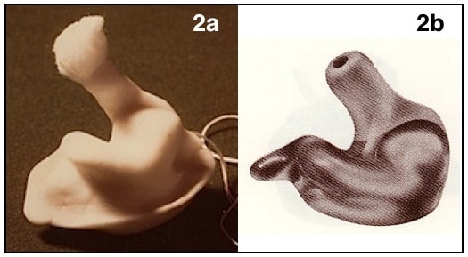
Figure 2. Ear impression (2a) and finished product produced from and investment of the ear impression (2b). The finished product could have the electronics imbedded into the earmold, as in a custom-molded hearing aid (ITE, ITC, CIC).
canal concha and varying depths of the ear canal (Figure 2a) and resulting in a finished product (Figure 2b). Without question, custom earpieces have been the mainstay of directing amplified sound from the hearing aid toward the tympanic membrane.
The custom earpiece, made from an ear impression, is often presented as an exact replica of the ear canal. Such a statement is troubling because the ear canal is considered to be fairly dynamic in its configuration, and an impression of the ear has difficulty capturing these dynamics{{1}}[[1]] Termeer, P. (1992). Ear canal expansion using different ear impression materials. Unpublished Report, Philips Hearing Instruments, Eindhoven, The Netherlands[[1]],{{2}}[[2]] Oliviera, R., Hammer, B., Stillman, A., Holm, J., Jons, C., and Margolis, R. (1992). A look at ear canal changes with jaw motion. Ear and Hearing, Vol. 13, No. 6, 464-468[[2]],{{3}}[[3]] Staab, W. J. (1993). March. XP peritympanic ear impression results on 100 plus patients. Paper presented at the Colorado Otology/Audiology Conference, Breckenridge, Colorado[[3]],{{4}}[[4]] Staab, W. J., and Martin, R. L. (1994). Taking ear impressions for deep canal hearing aid fittings. The Hearing Journal, Vol. 47, No. 11, 19-26[[4]],{{5}}[[5]] Oliviera, R. (1995). The dynamic ear canal. In Ballachanda B., Ed. The Human Ear Canal. San Diego: Singular Publishing Group, Inc., 83-111[[5]],{{6}}[[6]] Pirzanski, C. Z. (1996). An alternative impression-taking technique: The open-jaw impression. The Hearing Journal, 49(11), 30, 32, 34-35[[6]], nor always maintain the appropriate shape following removal of the impression and prior to fabrication{{7}}[[7]]Agnew J. (1986). Ear impression stability. Hear Instr 37 (12):8–8,11–12,58–58[[7]].
How much the actual ear impression varies from the dynamic ear canal depends on a number of issues: the chemical composition of ear impression material, whether the impression was taken during mandibular or other head movement (excessive or normal), the viscosity of the impression material, the shore hardness (durometer) of the ear impression material, the type of syringe used, the pressure applied by the syringe, the softness or hardness of the ear canal tissue, whether the ear impression was complete, how much of the ear canal replication is/was required, the temperatures/conditions of shipping, and other justified questions. A sampling of earmolds (no ITE, ITC, or CIC samples included) is shown in Figure 3.
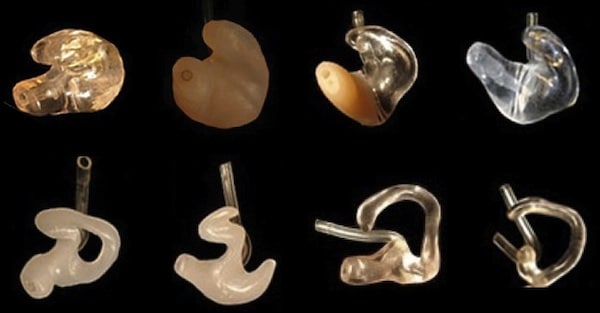
Figure 3. A sampling of custom earmolds for hearing aids. Some are made of hard acrylic, some are soft material, and some are a combination. The shape of that part showing in the bowl of the ear, as well as that being directed into the ear are designed for different purposes: cosmetic, function, or both.
In summary, “an ear impression is an accurate representation of the ear canal, related only to the specific conditions of impression taking”{{8}}[[8]] Staab, W. J., and Martin, R. L. (1994). Taking ear impressions for deep canal hearing aid fittings. The Hearing Journal, Vol. 47, No. 11, 19-26[[8]]. In the past, the custom earpiece has sometimes been seen as an albatross around the neck of successful hearing aid fitting and a barrier to market penetration. However, that does not mean that it has to be, and procedures have been, and continue, to be developed to move away from the myriad of issues that confronted custom earmolds in the past.
Imaging
Imaging has involved two primary approaches: (1) laser/photo scanning of ear impressions, and (2) 3D imaging of the ear canal.
Laser/Photo Scanning of Ear Impressions
That ear impressions and the finished custom-molded product are such a significant issue is evident from the expense invested by the industry to develop photo scanning of ear impressions (Figure 4). This led to shell-making improvements based on fabrication of the earpiece using these dispenser office measurements of the ear impression, rather than fabrication from the ear impression investment.
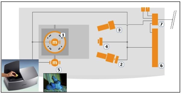
Figure 4. Ear impression scanner from Siemens. 1) Turntable to hold impression. 2) Projector to place a color code slide on the impression, used by the color camera for the 3D reconstruction algorithm. 3) A digital color camera to take color-coded images from different angles. A second task is to take normal images, without color codes. 4) LED light source illuminates the ear impression, and also to project a grid pattern of colored light onto the ear impression. 5) Motors turn and tilt the turntable. 6) Control unit includes the firmware responsible for controlling the scan hardware, and also exchanges information via USB between the scanner and the PC. 7) USB hub for camera, PC, printer, etc.
The ear impression is attached to a magnetic holder that is placed onto a turntable in the scanner and images are captured using a digital camera. Multiple images are taken from different positions and angles. The images (roughly 30-40) are then combined to create a 3D point cloud, which is visible on a screen. It is this information, rather than the ear impression, that is sent to the manufacturer for fabrication of the earmold.
This process is believed to have improved the fabrication speed (data is electronically sent), quality, and tracking of the finished product such that it is closer in configuration to the taken ear impression in its dimensional characteristics. This allows for controlled shell thickness, for reworking the product without having to make additional ear impressions, the elimination of changes due to buffing, migration of the acrylic as it is being poured and during setup, shipping of the actual ear impression, etc. This process appears to be good for production, especially for small custom-molded products where real estate is critical.
A caveat that cannot be ignored, however, is that there are no assurances that the scanned ear impression is appropriate to begin with. When not, a poor impression is cataloged into the database. Garbage in, garbage out is just as applicable to this process as it is for traditional procedures. There is no guarantee that scanning technology of the ear impression can solve the earpiece fit/comfort issues.
3D Digital Ear Scanning
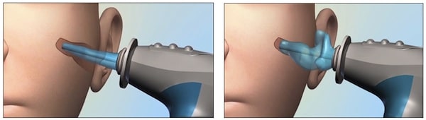
Figure 5. 3D digital ear scanner from Lantos. The left image shows the insertion of the soft conforming membrane into the ear canal. The right image shows the soft conforming membrane expanded with a water based optical dye to the shape of the ear canal. An internal scope advances and retracts to generate a 3D map of the ear canal in real time.
Three-dimensional digital impression taking of the ear canal eliminates the need for ear impressions. Scanning takes less than a minute per ear and files can be simply e-mailed to the device manufacturer. As an example, the scanner from Lantos Technologies uses a portable video otoscope/3D scanner in a single unit (Figure 5). The video otoscope facilitates the insertion of a soft conforming membrane into the ear canal, then is filled with a water-based optical dye and expands to the shape of the ear canal. The intensity of two different wavelength bands of fluorescent light is measured as they travel through an absorbing water based medium. The scope advances and retracts to generate a 3D map of the ear canal in real time. The pressure in the scanner can be varied to investigate movement of the ear canal that could be significant to fabricating the finished product. When finished, liquid is drawn out of the soft conforming membrane to its original size for removal. Computer then sends scanned data electronically to the hearing aid manufacturer.
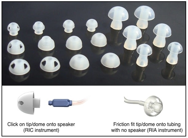
Figure 6. A sampling of stock fitting tips/domes used with RIC and RIA configured hearing aids. Some have a “click” fit (primarily with RIC units), and others, especially RIA hearing aids, have a friction fit, slide-on tip/dome.
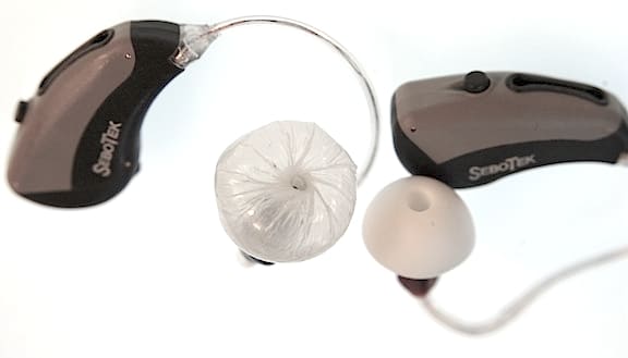
Same Session Coupling (Universal earpieces)
Same-session coupling of the hearing aid to the ear mostly involves the use of “stock” soft tips of varying sizes and shapes that friction fit or click onto a hearing aid sound tube (Figure 6). These are common with either RIC (Receiver In The Canal) or RIA (Receiver In The Aid) hearing aids. These are not custom-made to the ear canal, but are soft and pliable to conform to the ear canal to direct the sound to the tympanic membrane. Some tips are vented (open fit) and others are solid to avoid acoustic feedback or to provide other acoustical advantages. Same-session earpiece use accounts for approximately 50% of all hearing aids sold currently.
Another proposed variation of a same-session coupling approach uses an expandable piece in the ear canal. In one such case, an expandable balloon in the ear canal has been suggested to provide essentially a one-size-fits all approach{{9}}[[9]]Staab, W.J., Ricketts, T., Ambrose, S., Gido, S., and Schulein, R. A voice activated, inflatable, self-regulating, balloon ear coupler. HEARING REVIEW, Vol. 18, No. 6, pp 16, 18, 23, June 2011[[9]]. The goal is to manage hearing aid coupling with total comfort using a single size unit that inflates using a pure tone generated by the hearing aid, to the “push back” comfort of the ear canal. This invention harvests the power of the hearing aid speaker/receiver, and uses this to perform work – in this case, to inflate a folded balloon, similar to an air bag in a car (Figure 7){{10}}[[10]] Staab, W.J., Ambrose, S., Ricketts, T., Leuder, T., D’Onofrio, K. (2013), Self-inflating sound-activated balloon-style hearing aid coupling device. American Auditory Society Technical and Scientific Meeting, March 8, Scottsdale, AZ[[10]]. Such a sound coupler to the ear offers movement in total concert with any ear canal displacement. Additionally, such a device is expected to provide improved retention and sense of security of the earpiece. The design purpose of the expandable ADEL balloon was to provide a universal alternative to many current fitting coupling eartips.
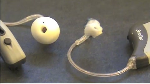
Figure 7. Sound inflated folded balloon ear coupler video (ADEL Inflating). Sound-activated inflatable ear coupler (folded balloon) on the right. The left shows a typical “stock” earpiece of an occluded configuration that is 10 mm in diameter. This experimental balloon size would fit ear canal sizes from about 4 mm to 15 mm+. This video is from a presentation given at the American Auditory Society in March 2013 (see reference 10).