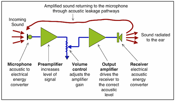
Figure 1. Basic understanding of gain. The input to a hearing aid is subtracted from the output. The result is the gain of the instrument.
The use and understanding of hearing aid gain is common among hearing professionals. It is essentially the difference between the level of a sound into a hearing aid versus the amplified level of what comes out of the hearing aid (Figure 1). However, other gain descriptions are helpful in understanding hearing aid performance. Two that are especially helpful are maximum stable gain (MSG) and added stable gain (ASG).
To understand why these additional gain definitions are of importance, it is necessary to review the primary reason they are discussed. The reason is that they relate to hearing aid acoustic feedback and hearing aid use.
Acoustic Feedback

Figure 2. Acoustic feedback pathway resulting from the output signal at the receiver returning to the microphone and being reamplified.
Acoustic feedback (also known as audio feedback, simply as feedback, or the Larsen effect) is a special kind of positive feedback that occurs when a sound loop exists between an audio input and an audio output. In a hearing aid, a signal received by the microphone is amplified and passed through the hearing aid speaker (Figure 2). The microphone can receive sound from the speaker again, amplified further, and then passed out through the speaker again under a variety of conditions, often related to sound leakage around the earmold/coupling device in the ear canal. The frequency of the resulting sound is determined by resonance frequencies in the microphone, amplifier, and speaker. The sound is readily recognized as a loud squeal or screech. Hearing aid professionals call it “feedback,” and it is the bane of many hearing aid fittings.
This positive feedback phenomenon has a property that results in a signal tending to reinforce itself and grow larger. It is perhaps most frequently encountered in audio amplification systems where a loudspeaker and microphone are involved (essentially the same as with hearing aids). Placing the microphone near the speaker creates a positive feedback loop, and the result is a sound that grows louder and louder. Because the majority of noise in an electrical system is high frequency, the sound output of the system becomes the high-pitched squeal that is so uncomfortably loud. Positive feedback was used at one time to increase gain – that was before high-gain circuits became available.
How Much Gain Is Present Before Feedback?

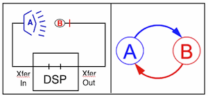
Figure 3. Acoustic feedback resulting from a closed signal loop between the hearing aid speaker output (A) and the input microphone (B). Feedback exists between the two parts when each affects the other. The circle on the right illustrates the continuous repetitive cycle leading to the feedback.
Although a number of feedback-reduction techniques have been developed for hearing aids, acoustic feedback continues to be a problem. When a sound signal is captured by the microphone, and subsequently amplified and played back through the hearing aid speaker, the speaker output is often fed back to the microphone through acoustic coupling (often described as “leakage” of the amplified sound around the coupler in the ear). The existence of such an acoustic feedback path results in a closed signal loop (Figure 3) that limits the performance of the hearing aid in two ways. First, it limits the upper level of amplification that can be applied if the system is required to remain stable (referred to as the maximum stable gain, or MSG). Second, the sound quality is affected by occasional howling when the MSG is exceeded, or even when the system is operating below the MSG, as evidenced by ringing and/or excessive reverberation.

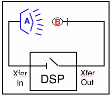
Figure 4. Open loop resulting in no acoustic feedback between the hearing aid speaker output and the input microphone. The loop gain is the intrinsic value of the amplifier without feedback.
The loop gain is the sum of the gain, expressed in dB, around a feedback loop. It is calculated by imagining that the feedback loop is broken at some point (Figure 4), and then calculating the net gain if a signal is applied. If the loop is broken, it is “open,” and the open loop gain is said to be the intrinsic gain of the amplifier without feedback. If the loop is closed, the loop gain is the overall actual gain with feedback. As an amplifier, the open loop model is not practical because the very high gain that results creates poor stability of amplification. Essentially, what this means is that closing the feedback loop turns an amplifier where gain is too high, into a useful one (where gain is manageable). As a result, closed loop amplification systems that allow for control of the amplifier are employed in hearing aids. The open loop is used as a calibration, primarily for characterization of feedback to estimate the feedback path.
Feedback Can Be a Wonderful Thing? – How to Get More Stable and/or Added Usable Gain
We have already confirmed that acoustic feedback limits the maximum gain that can be applied to a hearing aid. The solutions to managing feedback fall into two broad categories: 1) gain reduction, and 2) feedback cancellation. Gain reduction provides a simple solution and essentially always works if the gain is reduced sufficiently, but the loss of amplification may also reduce the audibility of speech.

Figure 5. Simple block diagram of a closed-loop feedback amplifier. A feedback loop is created with some portion of the output returned to the input. If the signal is inverted, the system has negative feedback. If not, the feedback is said to be positive.
With feedback cancellation using digital signal processing, the feedback path is modeled mathematically and subtracted from the microphone signal. Feedback cancellation (mostly done adaptively today) can improve the stability of the hearing aid and allow an additional 10 to 15 dB additional gain over an instrument or hearing aid setting that does not use feedback cancellation, and with no detrimental modifications of the hearing aid response expected. Feedback cancellation applies a portion of the output signal to the input, resulting in the overall gain and response determined mostly by the feedback network (Figure 5). Feedback cancellation is also identified as a feedback amplifier, and is currently the choice for managing feedback in hearing aids.
An overall goal in hearing aid design is to have an amplification system that allows high gain without acoustic feedback. While feedback cancellation appears to provide a near perfect solution to resolving the acoustic feedback concerns, it has its own problems. An adaptive feedback-cancellation filter is needed to model the dynamic changes in the feedback path. Algorithms associated with this are sensitive to tonal input signals (and may cancel the tone rather than feedback), room reflections, and non-linear distortion{{1}}[[1]]Kates, J. 2006. A primer on feedback cancellation in hearing aids, GN ReSound, Boulder, CO[[1]].
Using Feedback to Get More Gain
Figure 5 illustrates a block diagram of the simplest form of a feedback amplifier. A feedback loop is created when all or some portion of the output is fed back to the input. If the signal is inverted on its way around the control loop (output to input), the system is said to have negative feedback. If not, the feedback is said to be positive. Negative feedback is often deliberately introduced to increase the stability and accuracy of a system by correcting unwanted changes. A device is said to be operating open loop if no output feedback is being employed, and closed loop if feedback is being used. Ironically, with negative feedback, as information is fed back, the output becomes more stable. With positive feedback, as information is fed back, the output destabilizes and saturation tends to occur. Amplifiers with negative feedback depend less and less on the open-loop gain and eventually depend only on the properties of the values of the components in the feedback network.
This discussion can be somewhat confusing because it tends to mix discussion of how things function with op-amps to DSP (digital signal processing). In DSP, feedback is managed mathematically rather than through the use of hardware. And, it is mostly managed adaptively, meaning that it constantly models the feedback pathway. A limitation on feedback cancellation is the accuracy with which the feedback path can be modeled, because it can change readily. Additionally, the model and the procedures used to estimate the feedback path response should not cause any degradation in the hearing aid output.
Feedback in a Closed-loop System
The function of a feedback-control system is to ensure that the closed-loop system has desirable dynamic and steady-state response characteristics. Ideally, the closed-loop system should involve the following performance criteria:
- It should be stable
- Minimize the effects of disturbances
- Provide rapid, smooth responses to amplification changes
- Eliminate offset
- Avoid excessive control action
- It should be robust
Typically, it may not be possible to achieve all these goals because they involve inherent conflicts and trade-offs related to controller settings. Controllers can be located in a number of different places:
- In front of the system, before the feedback loop
- Inside the feedback loop, in the forward path, before the DSP
- In the forward path, after the DSP
- In the feedback loop, in the reverse path
- After the feedback loop
Each location has certain benefits and problems, taken into account by the system engineers. The primary goal is to bring the open loop below unity gain in order to keep things stable in the closed loop.
Next Week: Maximum Stable Gain (MSG) and Added Stable Gain (ASG) as they relate to hearing aid acoustic feedback.


Good article…but… according to my basic knowlege of mathematics 100-60 is 40dB of
gain, not 30. New math??