Is Your Hearing Aid a Beamformer?
 Broadfire versus Endfire Microphone Arrays
This post is the first in a series intended to provide cursory information about how multiple microphones (arrays, or beamforming hearing) are used to improve the SNR in hearing aids by focusing on the direction of the targeted sound. This process is called “beamforming.” Serious readers of beamforming can find a plethora of information on the Internet and other reference sources, and in much greater detail than will be found in this series.
Separating Speech and Noise
It is common for hearing-impaired individuals to have difficulty distinguishing between a speaker and background noise, both with and without hearing aids. Current hearing aid products promote beamforming, in the form of directional microphone hearing aids, as a method to focus on wanted, versus unwanted sounds, and in doing so, purport to improve the signal-to-noise ratio (SNR). Various approaches have been employed by design engineers to improve the intelligibility of speech in the presence of background noise (groups, traffic, events, etc.).
Beamforming
A graphic illustration of ideal sensitivity patterns between two different microphone setups is shown by the red lines in Figure 1{{1}}[[1]]Greensted, A., Delay sum beamforming, https://www.labbookpages.co.uk/audio/beamforming/delaySum.html, last modified, Oct. 27th, 2012[[1]].
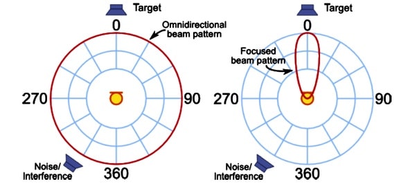
Figure 1. Sensitivity patterns for two different microphone setups. Explanation follows.
The diagram on the left shows the sensitivity pattern for an ideal omnidirectional microphone having equal sensitivity to signals from all directions, regardless of the signal type (target or interfering noise). The diagram on the right shows a sensitivity pattern that is highly focused toward the target sound, essentially eliminating that of the interfering noise. When applied to hearing aids when they are worn, the sensitivity pattern on the left is affected by the shadow created by the head, resulting in a pattern that is somewhat modified from that shown. The pattern on the right shows a very focused beam pattern using a microphone array (multiple microphones). Although the pattern shown is not normally found in hearing aids, it is available in some alternate listening devices. This “steering” and “shaping” of the microphone directivity pattern, as shown in the right image, is referred to as microphone array beamforming.
Acoustic Beamforming
Focusing sensitivity to sound can occur both in transmission and in reception. For hearing aids, the focus is on sound reception, which involves the hearing aid microphone(s). The goal is to create a hearing aid listening sensitivity pattern that responds to signals coming from the direction of the target sound, which is generally the person speaking. The microphones involved are omnidirectional, and beamforming can be accomplished:
- Physically (shaping and moving microphones),
- Electrically (using an analog delay circuit), or
- Mathematically (digital signal processing).
The focus of this post is on sound reception only, the way hearing aids operate, not on sound focusing transmission.
Beamforming Basics
Also called spatial filtering, beamforming is a signal processing technique used to transmit or receive a signal with a directional focus in mind – in other words, to selectively tune in to certain sounds. In general, beamforming can be applied to radio or sound waves and is involved in numerous applications, including radar, sonar, seismology, wireless communications, acoustics, and in biomedicine. For hearing aids, the focus is on sound waves and involves two or more microphones, or what is referred to as a microphone array.
Multiple-Microphone Arrays: Broadfire vs. Endfire
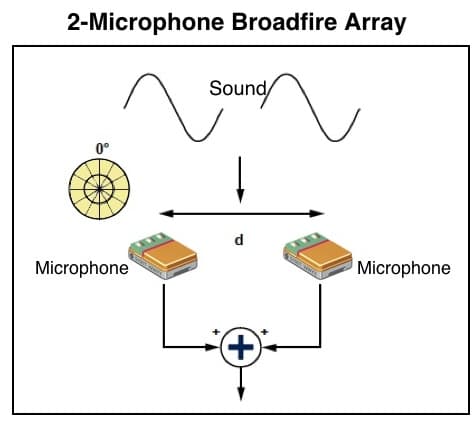
Figure 2. A 2-Microphone broadside array. This has practical application where multiple microphones (2 or more) each face the sound source. Implementation of broadside arrays can take place using basic processing because the microphones in the array are simply summed together. This array arrangement is not used in hearing aids.
Broadfire Arrays are such that a line of microphones is arranged perpendicular to the direction of sound waves (Figure 2){{2}}[[2]]InvenSense Application Note AN-1140, 2013. San Diego, CA[[2]]. This means that the microphones are facing broadside to the sound source. The spacing between the two microphone elements, identified as “d,” varies, depending upon the desired sound source separation. This arrangement does not lend itself to hearing aids because space is not available to put microphones side by side facing the sound source and with an appropriate distance between them. Additionally, a down side to a broadfire array for hearing aids is that sound is attenuated when arriving from the side of the array. Because sounds from the rear always match those from the front, nothing differentiates sound pressures coming from either the front or the rear. For the purposes of this post, broadside arrays are best suited for situations such as watching television where there is not much incident sound from behind, and a device can be designed that allows multiple microphones with appropriate distance between the microphones facing the sound source.
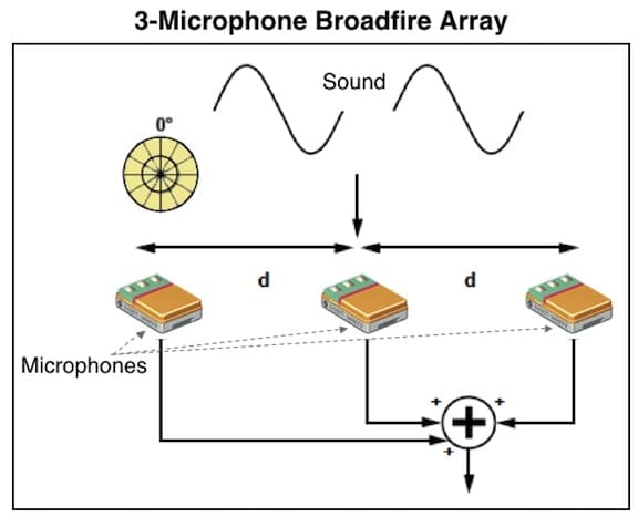
Figure 3. Additional microphones in a broadside array. Higher numbers of microphones in broadside arrays can achieve greater attenuation of sound from the sides of the array. Adapted from InvenSense Application Note AN-1140, 2013).
Adding additional microphones to a broadfire array – Figure 2 shows two forward-facing microphones in a broadfire array. However, additional microphones can be added in line, as shown in Figure 3. The advantage of additional microphones is to provide for greater attenuation of sound from the sides of the array. For example, if a 2-microphone array having a certain spacing between elements provides a 3-dB attenuation of sound from the sides, a 3-microphone array would attenuate those same sounds by 6 dB. Spacing between the microphones results in trade-offs between attenuation and the aliasing frequency, and steering to other angles are all beyond the scope of this post.
Still, Figure 4 shows that the direction from which a wave front originates has an effect on the time at which the signal meets each microphone in the array. Because the array’s output is created by summing all microphone signals, maximum output amplitude is achieved when signals originate from a source perpendicular to the array (center image), where they are correlated and reinforce each other. However, if the sound source is not perpendicular, but to the left or right, the signal reaches the microphones at different times. This results in a value that is less correlated, resulting in a lesser output amplitude.
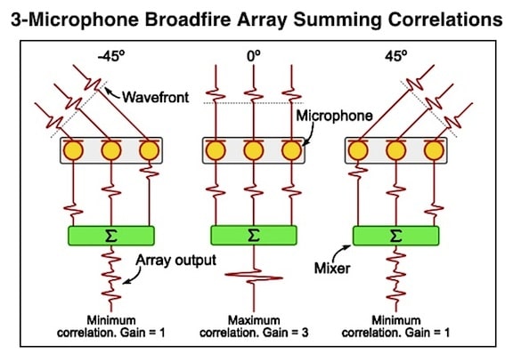
Figure 4. A 3-microphone broadside array. (Greensted, 2012).
Endfire Arrays consist of multiple microphones arranged in line with the direction of sound propagation (Figure 5). This 2-microphone array is the arrangement found in current hearing aids. Sound to the front microphone (the first that the sound reaches) is summed with an inverted and delayed sound from the rear microphone. The sound received by the rear microphone is delayed before the summation block. The distance “d” has a significant impact on the amount of front/rear sound reception. The subtraction (or, invert-and-sum) block is used to create cardioid (heart-shaped), hypercardioid, or supercardioid pickup patterns (Figure 6). In all of these patterns, sound from the rear of the array is greatly attenuated. The endfire array having two microphones, as shown, is referred to as a first-order delay-and-sum beamformer. Signals from the side are attenuated about 6 dB.
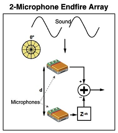
Figure 5. A 2-microphone endfire array commonly used in hearing aids. See text for explanation. Adapted from InvenSense Application Note AN-1140, 2013).
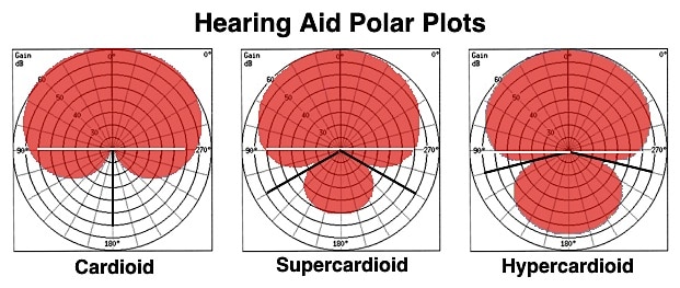
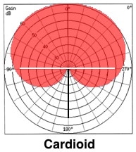
Figure 6. Endfire microphone array polar plots showing three different hearing aid polar patterns. The cardioid pattern shows no signal reduction from the front and theoretically cancels sound arriving at 1800.
Higher-Order Endfire Arrays
Higher-order endfire array beamformers can be formed by adding additional microphones in line with the first two (Figure 7). This shows a second-order (3-microphone) endfire beamformer. This results in more rejection of sounds from the rear and side, as shown in Figure 8. The disadvantage is that adding additional microphones requires a longer physical dimension in which the beamformer must be built, something not readily available in miniature hearing aids. A second-order endfire can achieve 12 dB of attenuation to sounds from the sides, without any change to the null, present at the rear of the array. A second-order behind-the-ear hearing aid was introduced by Siemens in 2002 (Figure 9){{3}}[[3]]Powers, TA, Hamacher, V. (2002). Three-microphone instrument is designed to extend benefits of directionality. Hearing Journal, 55(10):38-45[[3]], and an interesting endfire array concept by Etymotic Research, also in 2002 (Figure 10), provided a longer physical dimension and could be coupled to any type hearing aid, even though the cosmetics left something to be desired.
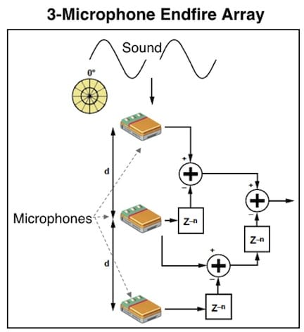
Figure 7. A 3-microphone (second-order) endfire beamformer where additional microphones extend the benefits of directionality.
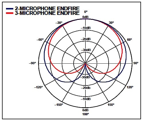
Figure 8. Polar plots of a second-order (3-microphone) endfire beamformer (red line) compared to a first-order (2-microphone) beamformer (blue line). The second-order beamformer array provides greater reduction of sounds from the side, and also from the rear.
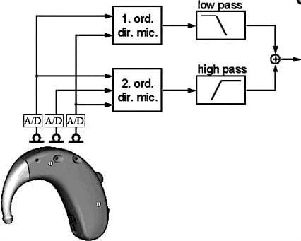
Figure 9. A second-order hybrid directional microphone introduced by Siemens in 2002. The outputs of the front and rear microphones are processed to form a first-order directional microphone, the output of which is low-pass filtered.
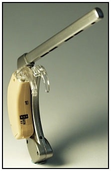
Figure 10. A multiple endfire array concept that could be utilized with any type hearing aid, behind the ear (BTE) or in-the-ear (ITE). (Etymotic Research, 2002).
Microphone distance and delay
The distance between the microphones, and the time delay for the rear microphone to respond, determine the polar pattern. This type of microphone array is termed a delay-and-sum beamformer. The sound picked up by the different microphones differs only in the arrival time, assuming it can be approximated by a plane wave. The signal from the rear microphone is delayed by the time it takes for the sound waves to travel between the two microphones. The spacing between the microphones determines the null frequency (condition of no, or reduced signal) and also the practical physical length of the microphone array. It can’t be too long because today’s hearing aids are rather small in size, resulting in practical industrial design limitations.
(Next week’s post will continue this series on beamforming and hearing aids).


