Western Electric 2-A Audiometer
 Most hearing care professionals have heard or read that one of the early audiometers for the measurement of hearing sensitivity was the Western Electric 2-A audiometer. Few have any idea what it looked like or what it did. This post is pleased to bring to readers some of the best detailed photographs of the 2-A audiometer. The 2-A was the followup design to the Western Electric 1-A audiometer
From the Western Electric 1-A to the Western Electric 2-A Audiometer
In 1914, Western Electric patented the electric audiometer, and produced the first commercially available electronic audiometer for the measurement of the sensitivity of hearing, the Western Electric 1A (Figure 1). This instrument allowed frequency testing using a specially designed earphone. With a price tag of $1500, it cost slightly less than a house. Designed by E. P. Fowler and R. L. Wegel, 25 units were sold in 1922. It allowed for hearing testing from 32 through 16,384 Hz{{1}}[[1]]Fowler E. P., & Wegel R. L. (1922). Audiometric methods and the application. Transactions of the 28th Annual Meeting of the American Laryngological, Rhinological and Otological Society, pp. 98–132[[1]]. As Berlin noted in his early hearing testing days at Johns Hopkins, it was mounted on wheels so it could be rolled to where it was needed{{2}}[[2]]Berlin, C. Hearing science and audiology, in History of Audiology, with Hall J. III, Margolis R., and Staab W. American Acad. of Audiology Annual Meeting, April, 2013[[2]].
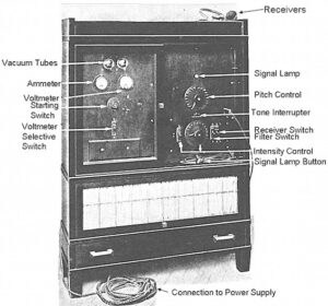
Figure 1. Western Electric 1-A audiometer.
Western Electric 2-A Audiometer
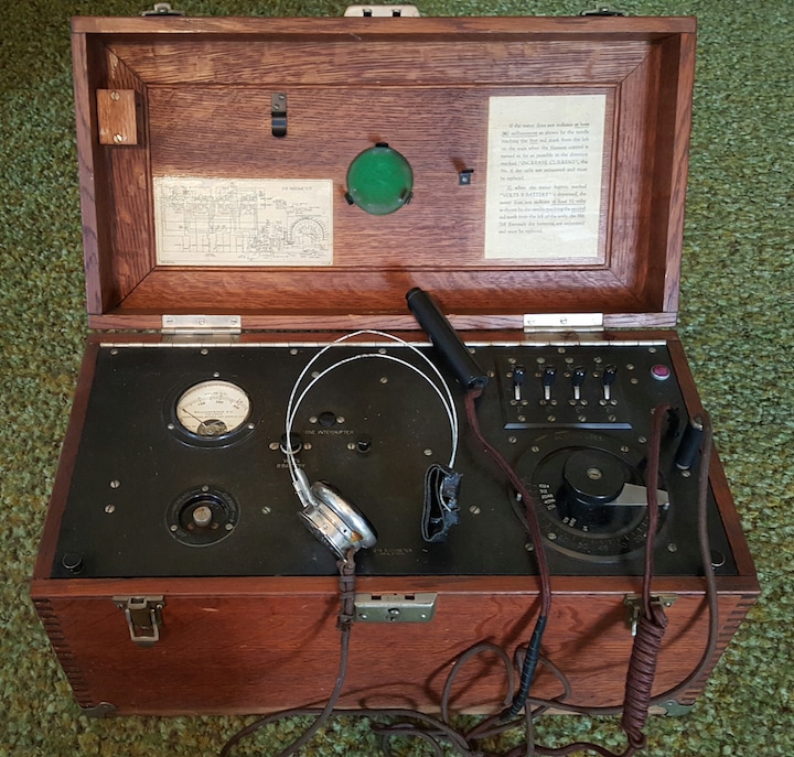
A short time later, 1923, the first widely-used audiometer at that time, the Western Electric 2-A Audiometer was produced (Figures 2 through 6). This unit was more portable, designed to meet clinical needs, and was less costly. It was also powered by dry cells. Early proponents in the 1920s and 1030s of the 2-A were otolaryngologists, although their enthusiasm was tempered by the fact that there was no standard calibration of the device{{3}}[[3]]Jerger, J. (2009) Audiology in the USA. Plural Publishing Co.[[3]]. In the early instruments, normal threshold values for each test frequency had to first be established to provide a reference. No standard reference levels existed. The instrument was limited to 8 frequencies at octave intervals between 64 Hz and 8,192 Hz. The intensity range was limited, and an additional booster amplifier was needed to determine the threshold of feeling.
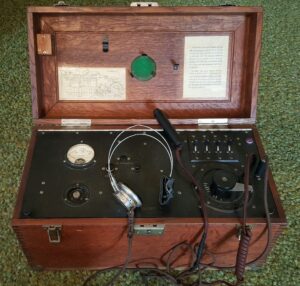
Figure 2. The Western Electric 2-A Audiometer.
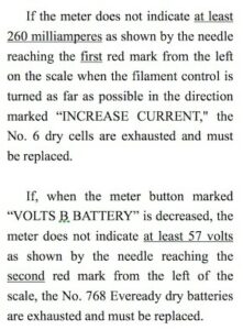
Figure 3. Duplication of the inside lid top, right side, that describes use of the A-2.
Battery check instructions were printed on the inside right lid and are duplicated in Figure 3, while Figure 4 shows the label that provided patent dates on the outside lid and a usage function that read: “Licensed as an Audiometer used only for plotting curves for hearing sensitivity.” The frequency of the tone produced was selected by switches to the rear behind the sensitivity knob (marked in decibels). A meter to the left provided a method for checking the batteries that powered the WECO or “Peanut” valve/vacuum tube (Item A0614), as part of the circuitry. Earphones for listening, and a hand-held push button used by the subject, indicated when the sound was heard. An inside view of he electronics of the A-2 is shown in Figure 5.
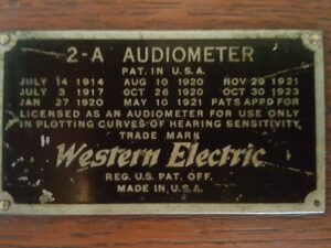
Figure 4. Patent data and identification of the device “Licensed as an Audiometer used only for plotting curves for hearing sensitivity.”
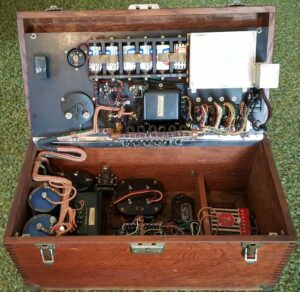
Figure 5. Electronics of the Western Electric 2-A Audiometer, with the plate raised.
By 1928, bone-conduction testing capabilities became a standard component of all Western Electric audiometers following its development in 1924 by Knudsen and Jones and produced by Sonotone Corporation{{4}}[[4]]Bud, R., and Varner, D.J. (Eds). (1998). Instruments of Science: An Historical Encyclopedia, The Science Museum, London and The National Museum of American History, Smithsonian Institution, pp. 39-41[[4]].
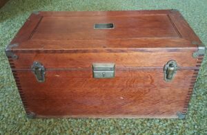
Figure 6. Wooden case in which the Western Electric 2-A audiometer was housed.
The origin of audiometric zero reference standards was based on the hearing survey in 1935 and 1936 conducted by Beasley as part of a general health survey sponsored by the U.S. Public Health Service. A Western Electric 2A audiometer using Western Electric 552-W earphones was used to record audiometric sensitivity thresholds of 4,662 adults reported to be clinically normal, having no medical history of otological disease or other abnormality. The number was then reduced by eliminating persons who’s hearing sensitivity was greater than 15-20 dB. The earphones were calibrated on a “conventional type closed coupler,” assumed to be the NBS (National Bureau of Standards) 9A — assumed, because no description was provided. This information formed the bases for the ASA (American Standards Association) 1951 standard for audiometric zero reference level{{5}}[[5]]Glorig, A. (1966). Audiometric reference levels, The Laryngoscope, Vol. 76, Issue 5, pages 842-849[[5]].
It was not until 1978 that the first ANSI Standard Method for Manual Pure Tone Audiometry (measurement procedures and conditions) was published.
Little Known Trivia
Western Electric 2-A Audiometer Used to Test Intensity Levels of Airplanes
In an attempt to determine panels light enough for use in airplanes, but of considerable opacity to sound, the U.S. Army Air Corps and the Bureau of Aeronautics of the Navy used a Western Electric 2-A audiometer as a measuring instrument for sound intensity. By making use of the masking effect of noises on the audiometer tones, a fair idea of the reduction factor of different airplane cabins was obtained. It was determined that from audiometer measurements, the average close-up intensity of the noise of an airplane in flight is about 95 sensation units. If a cabin could be built with a reduction factor of 35 units, the intensity of the noise within the cabin (670 units) would be about that in a railway coach in motion. The airplanes used for the different cabin tests were a Fokker trimotor plane from the Army Air Corps, and a Ford trimotor plane from the Navy{{6}}[[6]]Bureau of Standards Journal of Research, V. Tests in airplanes in flight, Vol. 2, 1929, 903[[6]].
Credit
This audiometer shown in this post belongs to Lewis Addison, audiologist and owner of HearTech, who is attempting to determine the value for this piece of history. He has provided these excellent photos of his Western Electric 2-A audiometer. If anyone has an idea as to its value, the suggestion would be appreciated. Contact us here at Hearing Health and Technology Matters and we will pass the information along, or send the information to [email protected], author of this post.