
HEARING LOOPS – 3 COMPONENTS and 3 E-Z STEPS!
Norman Lederman, M.S., Director of Research & Development, Oval Window Audio, Nederland, CO
Introduction
In the realm of “hearing assistance”, induction loops (more recently known as “hearing loops”) have a history spanning well over 50 years. Much has been written about this technology and related devices, including: how they work, pros and cons, hearing aid compatibility, new developments, technical standards, high profile initiatives & installations, and enthusiastic responses from the many hard-of-hearing people who benefit from this venerable approach to providing cost-effective hearing accessibility.
The author refers readers interested in the aforementioned topics to the many articles, postings and publications that have covered these areas in depth. Two great places to start are: www.hearinghealthmatters.org, and www.hearingloss.org, using the search phrase: “loops”. Another informative resource is: www.hearingloop.org that includes direct links to hearing loop manufacturers.
The purpose of this article is to “cut to the chase”…succinctly responding to five questions often raised by inexperienced and/or non-technical loop enthusiasts who wish to set up a small area hearing loop system:
- Can I make a hearing loop by attaching a wire to a TV or stereo?
- How do I loop a TV room?
- Can I easily loop a small office or conference room?
- Is it possible to set up a small area hearing loop where there is no AC power available?
- Is there a portable hearing loop I can use for a very small area, such as: a car, desk, bank teller’s window, or information counter?
Note: Covering areas greater than 100 feet in perimeter, and complex installations addressing: audio system design, loop signal confidentiality, carpentry, and/or the running of loop wire inside floors, walls or ceilings should be referred to professionals.
First…a quick review of hearing loop components (Figure 1)
The three components of a small area hearing loop system are :
- The loop wire, or loop pad (a loop pad has wires sandwiched between two layers of cloth typically measuring 15” x 15”) that is placed or installed in the listening area.
- The loop amplifier + AC adapter that powers the system.
- The signal source (TV, microphones, computer, telephone or other signal sources).
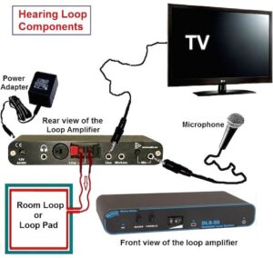
Figure 1. The three components of a small area hearing loop system: wire loop or pad, loop amplifier, and signal source.
What makes a loop amplifier “special”
A brief explanation of what makes a dedicated hearing loop amplifier “special” will answer the first frequently asked question, “can I make a hearing loop by attaching a wire to a TV or stereo?”
The typical loop wire has an electrical resistance measuring only 1 Ohm or less. TVs and stereo (or surround sound) systems are designed to power headphones and loudspeakers with a minimum resistance of 4 to 8 Ohms. Attaching a loop wire to a system that is not designed to accept it can result in damage to the amplifier.
Even if a correct electrical match is made (using a thinner or multiple turn wire), performance will suffer because hearing loop amplifiers (and their matching loop wires) are designed to transmit with a signal strength (and other technical parameters) uniquely specified by international standards.
3-E-Z STEP SET UPS
1. TV Room (Figure 2)
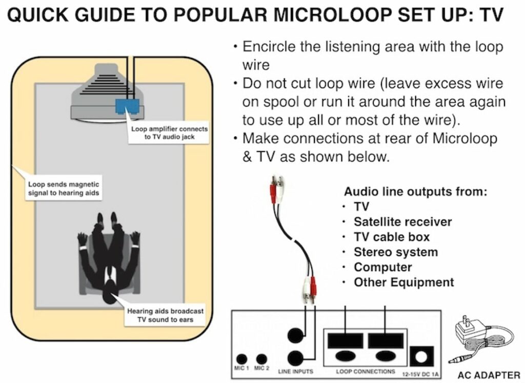
Figure 2. Quick guide to a TV Microloop set up.
- Place the loop wire around the immediate listening area; tucking/taping under carpeting, area rug, or furniture (alternatively, place the loop pad within two feet of the listener’s hearing aids).
- Connect the loop wire or loop pad to the loop amplifier.
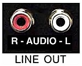
Figure 3. Image of a TV audio line output used to send the audio signal to a wire loop or pad.
- Using patch cords provided with the system, connect the loop amplifier to the TV’s audio line output jacks (Figure 3 shows one example). If not available on the TV, connect to the audio line outputs on the cable box or satellite receiver. In the event there are no audio line output jacks on the TV system, look for a “digital audio” output jack on the TV (Figure 4), and contact the hearing loop system dealer or manufacturer to purchase an inexpensive and compatible “digital to analog” converter (DAC) and connecting cable.
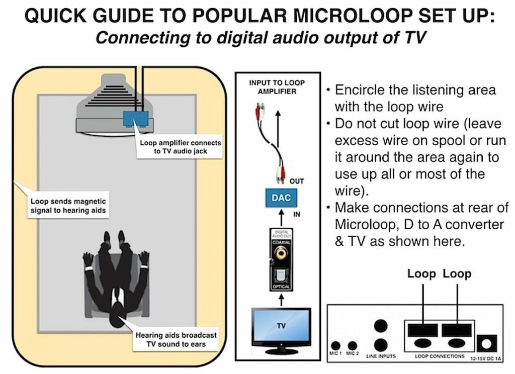
Figure 4. Arrangement for sending an audio signal from a TV to a wire loop or pad when the TV uses a digital audio output.
Notes:
- If there are no easily accessible TV audio line outputs, small microphones are available that may be easily Velcro’d to the TV’s loudspeaker.
- In situations where the loop wire cannot be easily run under carpeting, area rugs or furniture…using self-adhesive clips or tucking behind non-metallic self-adhesive molding, the wire may be placed around the perimeter of the room, or around one wall near the listener. Ceiling mounted loop wires should not exceed 12 feet in height.
- Microphones and/or other signal sources (e.g., computer or telephone audio outputs) may be easily interfaced with a TV room hearing loop.
- Loop pads may be used instead of loop wire for single listener fixed chair/sofa applications (hearing loop manufacturers typically recommend not using more than two pads per amplifier).
2. Office/meeting Room (Figure 5)
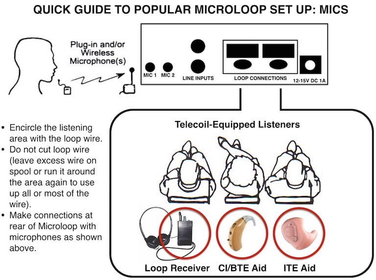
Figure 5. Quick guide for an office/meeting room microphone set up (plug-in or wireless microphone).
- Place the loop wire around the immediate listening area; tucking/taping under carpeting, area rug, or furniture (alternatively, place the loop pad within two feet of the listener’s hearing aids).
- Connect the loop wire or loop pad to the loop amplifier.
- Place the microphones (clip on or table top mics) as close as possible to the sound sources (Y cords are available to expand the number of microphones that may be used).
Notes:
- Perimeter loops “spill” their signals outside the looped area, so if close proximity rooms are being looped, or confidentiality is a concern, these conditions must be reviewed with the hearing loop dealer or manufacturer.
- In situations where the loop wire cannot be easily run under carpeting, area rugs or furniture…using self-adhesive clips or tucking behind non-metallic self-adhesive molding, the wire may be placed around the perimeter of the room, or around one wall near the listener. Ceiling mounted loop wires should not exceed 12 feet in height.
- Other signal sources (e.g., computer or telephone audio outputs) may be easily interfaced with an office/meeting room hearing loop.
- For scenarios without a conference table, microphone extension cords may be added, or contact the hearing loop dealer or manufacturer regarding compatible wireless clip on and “pass around” (hand held) microphones.
Applications where there is no AC power (e.g. outdoor events and vehicles):
Practically all small area hearing loop systems (as described in this article) are powered by AC adapters that connect 12 to 15 volts DC to the loop amplifier. For situations where there are no AC outlets, “cigarette lighter power cords” are readily available for powering a hearing loop system from a vehicle’s 12 volt battery. Installing a loop wire inside vehicles can be complicated, but setting up a small loop amplifier and connecting it to a loop pad placed on a car seat is straightforward and easy to evaluate. If this application is of interest, contact the hearing loop dealer or manufacturer to discuss the power cord and noise canceling microphones.
3. Very Small Area and One-on-one Portable Applications
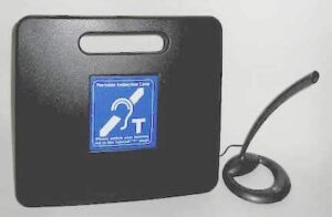
Figure 6. One-on-one portable wire loop integrated into a small , portable, rechargeable system.
When used as such, all three components of a hearing loop system are conveniently integrated into a small, portable, rechargeable system (Figure 6).
- Place the unit on a counter or table with the external microphone (clip on or table top mic) set up as close as possible to the sound source.
- Situate the telecoil-equipped hearing aid user within a few feet of the unit (typically standing at a counter or sitting at a desk/table).
- For portable applications, the unit is recharged after 5-7 hours of use. For fixed applications, the unit is left plugged into an AC adapter.
Notes:
- Using Y cords, multiple microphones may be used with this system for wider sound pick up (e.g., conference table-single listener applications).
- For vehicle single listener applications, the unit is typically placed next to the listener, or in a shoulder bag behind the car seat’s headrest, with noise canceling microphone placed on the driver/passenger.
Additional Tips
- While any manually switched telecoil-equipped hearing aid may be used to check the performance of a hearing loop, inexpensive loop receivers with headphones & signal indicators are available to check sound quality and to confirm proper peak signal strength (professional loop installers certify their work, using field strength meters calibrated to the latest IEC 60118-4 standards{{1}}[[1]] Electroacoustics – Hearing aids – Part 4: Induction-loop systems for hearing aid purposes – system performance requirements. IEC 600118-4, 2006[[1]]). These receivers are popularly used by hard-of-hearing listeners who do not have loop-compatible hearing aids.
- When possible, a “listening check” should be performed on site before the loop system is installed. On rare occasions, a planned hearing loop location may have excessive levels of environmental electromagnetic interference (EMI) generated by various sources, including the building’s wiring and local power lines. Frequent sources of EMI are light dimmers, easily remedied by switching them fully On or Off.
- All loop installers are urged to temporarily lay out/tack up and fully test the system before final installation occurs, checking performance as well as interference with, and from, existing systems.
- The hearing loop systems described in this article transmit signals that are directional. Listeners should be encouraged to slightly shift their seated or standing positions for the best loop signal reception.
In conclusion…small area hearing loops are easy and fun to set up and use, and experimentation is encouraged! When in doubt, a call or email to the hearing loop dealer or manufacturer can resolve practically any issue or question that arises.
Acknowledgements: Mr. Lou Touchette (hearing loop advocate, installer and head of the “Let’s Loop Tucson” movement) for reviewing and enhancing this article.
Norman Lederman
With degrees in audio engineering and physics from American University, Norman Lederman’s professional career began with technical positions at Washington DC area recording studios. In 1977 he moved to Gallaudet University’s Model Secondary School for the Deaf (MSSD) to maintain audiometric systems and student hearing aids. During his tenure at MSSD Lederman developed and taught courses on the science of sound and hearing aid technology. He converted his office into a “Multisensory Sound Lab” complete with a floor that vibrated with music and speech, and colorful visual displays of sound — becoming a popular campus attraction and useful tool for music, speech, and science classes.
Lederman spent a summer in the United Kingdom where he was first exposed to hearing loop technology that was routinely used in many institutions and public venues.
In 1984, Lederman left MSSD to form Oval Window Audio, a research, development and manufacturing company specializing in hearing loop technologies and special products like the Multisensory Sound Lab. Over the years, his company has been the recipient of research grants and awards from the National Institutes of Health and U.S. Department of Education.


What an informative column. Very useful for consumers. Thank you Norman Lederman for taking the time to write it and thank you Dr. Staab for giving him the space in your HHTM column. Consumers continue to be surprised how well they are able to hear in a hearing loop be it at home or in a public place. The most often question I get when I speak to consumers around the country is why did my audiologist or hearing care provider not tell about this? And it is worse when I am the one who has to tell them that they do not have this low cost t-coil or telecoil option in devices they spent good money on. Do you have any suggestions how we could tackle that problem?
Thank you for your positive response to my article. I too am sadly surprised when I am contacted by hearing aid users and hearing health care providers who are not aware of the potential usefulness of this basic technology. In response to your question, I’d have to say that this problem has been “tackled” and steady progress is being made. For those of us who were around when telecoils almost disappeared from hearing aids in the USA (and induction hearing loop products were not readily available), very impressive progress has been made in recent years. Thanks to people like you, and activists & organizations like the Hearing Loss Association of America; telecoils & loop products are being implemented like never before, technical standards are better, and awareness continues to grow, albeit slowly. It seems to me that “evolution” can be painfully slow, but as long as we’re moving in the right direction…positive outcomes are assured!
My grandma might have to look into something like this. She does watch a lot of TV so I think it would help her with that. Anyways, we’ll look into getting something like this for her sooner than later.