 By Wayne Staab and Steve Armstrong
In Bluetooth 101 – Part II, the discussion introduced concepts of connectivity of Bluetooth to other devices. This, Part III of the series, will expand on this connectivity: how it occurs, what is required, what happens when Bluetooth devices come in range of each other, and how they connect.
Wayne’s background can be seen below. Steve Armstrong, B. Eng. Electrical, started his career designing chips for hearing aids. Taking a systems view of each design element naturally led to developing a deep understanding of the acoustics and psychoacoustics involved in successful amplification. Today, building on his years of hardware experience, Steve provides strategic engineering services in the areas of algorithm, firmware, and fitting software development through his company, SoundsGoodLabs.
Pairing of Bluetooth Devices
General Process of Pairing Bluetooth Devices (Figure 1)
Make certain that the Bluetooth device is set to the “on” position.
Place the Bluetooth device in “discovery mode”
- When a Bluetooth-enabled device is “discoverable,” on the 2.4-GHz band, other Bluetooth devices can detect, pair, or connect to it.
- To prevent other Bluetooth devices from identifying your device, place it in the un-discoverable mode.
Search/Inquiry
- This is to inquire about other Bluetooth-enabled devices within range that are in the discovery mode.
- If several Bluetooth devices are set on discoverable mode, they all have the ability to search for and locate each other so long as they remain within range.
- The scanning device listens in on known frequencies for devices that are also actively inquiring. When an inquiry is received, the scanning device returns to the device that recognized its signal a response with the information needed for the inquiring device to determine and display its connection information.
- When in this mode, your device can be detected by other Bluetooth devices within a limited distance, and your device will search for devices within this limited distance as well.
Pairing (implies acceptance of the connection)
- Bluetooth pairing is a process by which two Bluetooth devices “see” each other for the first time, which creates a unique lasting connection between the specific devices.
- In many cases, when Bluetooth-enabled devices are within range of each other with Bluetooth turned on, they will establish a connection fairly quickly. But, if it doesn’t happen automatically, follow the basic steps provided here.
- Passkey: This is an authentication key used to establish a link between devices. A passkey is similar to a password that both devices accept. However, the passkey is used only once: you enter the passkey once and won’t need to remember it.
- Pass codes are usually found in the manual of the Bluetooth device
- Once paired, some kind of confirmation is given – usually a visual or auditory signal
- Pairing and Bonding: For security reasons, it is necessary to be able to recognize specific devices and thus enable control over which are allowed to connect to a given Bluetooth device. At the same time, it is useful when Bluetooth devices are able to connect without user intervention (for example, as soon as they are in range).
- To resolve this, Bluetooth uses a process called bonding, with a bond created through pairing. Pairing can be triggered either by a specific request from a user to create a bond (“Add a Bluetooth Device”), or is triggered automatically when connecting to a service where (for the first time) the identity of the device is required for security purposes. These two cases are referred to as “dedicated bonding” and “general bonding,” respectively.
- Once pairing has been successfully completed, a bond is formed between the two devices, enabling those two devices to connect to each other in the future without requiring the pairing process to confirm the identity of the devices.
- When desired, the bonding relationship can later be removed by the user.
- Some pairing mechanisms require a PIN identification while others are more simple, accepting Secure Simple Pairing (SSP), and generally do not require a passkey for connecting.
Connection
- Once pairing is made, the device you want to connect to should appear in the Bluetooth Search Mode Menu on your device. Select the device to establish the connection.
- Your device provides some kind of indication of a successful connection.
- Reconnecting
- Pairing remains intact when any of the devices is powered off or taken out of the link range (10 meters, primarily).
- Even when closing a Bluetooth connection by turning Bluetooth off, your devices will remember the other devices when the connection is opened again. The steps needed to establish the connection should only be necessary during the initial linking of the devices.
- To re-establish an active connection when the Bluetooth device returns within range, often some action is required, such as pushing a Play/Pause/Pairing button.
- If a connection is not made within a certain time period, the Bluetooth device will shut off. It will have to be turned on to attempt the pairing again.
- Subsequent connections (other times/days, etc.) may automatically attempt to re-establish a link with the most recently linked Bluetooth device. If there is not an automatic linking, a manual connection may have to be reinitiated.
Bluetooth Piconets (Networks)
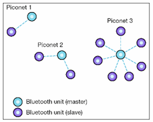
- A Bluetooth network starts with two connected devices, and may grow to eight connected devices. This connectivity of multiple devices, which occurs in an ad hoc (specific purpose) manner, is known as a piconet (Figure 2).
- Connecting multiple wireless devices within a short range is a primary advantage of Bluetooth.
- Devices can form a quick ad hoc secure piconet and start communicating with each other
- All Bluetooth devices on a piconet are peer units and have identical implementations.
- However, when establishing a piconet, one unit acts as a master (M) and the other(s) as slave (S) for the duration of the piconet connection.
- This connection can occur even when mobile, but must remain within the range (Figure 3)
-

Figure 2. Piconets can be simple: between two devices (Piconet 1), and growing to eight devices being connected (Piconet 3).

Figure 3. Piconet, showing that one unit acts as the master (M), and the seven units connected, as slave (S) units. All of these devices can talk to each other. The other devices in red outside the circle are not within the connecting range of the master, and would not be detected. Even though all of the slaves shown are within the range, not all have to be selected. However, eight (master and seven slaves) is the maximum that can communicate with each other.
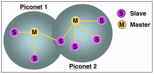
- A device can belong to more than one piconet, either as a slave or as a master. Multiple independent piconets with overlapping coverage areas form a scatternet (figure 4). A scatternet allows communication between piconets.
- The devices can switch roles, by agreement, and the slave can become the master (for a simple example, a headset initiating a connection to a phone will necessarily begin as master, as initiator of the connection, but may subsequently prefer to act as a slave).
- At any given time, data can be transferred between the master and one other device. The master chooses which slave device to address. But typically, it switches rapidly from one device to another in a round-robin fashion in order to give each device equal connectivity. Because the master chooses which slave(s) to address, it has a slightly lighter burden than a slave. Being a slave to more than one master is difficult (in more ways than one, as we all know).
Forming a Piconet
Two parameters are required to form a piconet connection. When the parameters of these two are combined, they form a FHS (Frequency Hopping Synchronization) packet.
- A frequency hopping pattern (or spectrum)
- A global ID defines the overall hopping pattern
- The master (M) algorithmically determines the hopping pattern
- Clock
- Synchronizes the frequency hopping to provide equal time for slave connectivity, and to avoid interference from other static non-hopping ISM systems (such as wi-fi networks) in the area, and from each other
- This manages the phase within the hopping pattern
The piconet’s radio channel is shared by a group of devices (S) that are synchronized to the master’s (M) clock and hopping frequency.
Next week’s post will continue, but concentrate more on how Bluetooth communicates, including frequency hopping synchronization (FHS).
Wayne Staab, PhD, is an internationally recognized authority in hearing aids. As President of Dr. Wayne J. Staab and Associates, he is engaged in consulting, research, development, manufacturing, education, and marketing projects related to hearing. His professional career has included University teaching, hearing clinic work, hearing aid company management and sales, and extensive work with engineering in developing and bringing new technology and products to the discipline of hearing. This varied background allows him to couple manufacturing and business with the science of acoustics to bring innovative developments and insights to our discipline. Dr. Staab has authored numerous books, chapters, and articles related to hearing aids and their fitting, and is an internationally-requested presenter. He is a past President and past Executive Director of the American Auditory Society and a retired Fellow of the International Collegium of Rehabilitative Audiology.


