Acoustic Application for Successful Hearing Aid Acceptance and Satisfaction
 A successful RIC hearing aid fitting, like many hearing aid fittings, is not necessarily related to any specific fitting formula, but is based on user satisfaction – the ability to hear, understand, and wear the hearing aid comfortably, without acoustic feedback, and in the presence of noise. And, with RIC-type hearing aids constituting 46% of current hearing aids worn{{1}}[[1]]MarkeTrak 9: A new baseline, Estimating hearing loss and adoption rates and exploring key aspects of the patient journey, Final Report, March 2015[[1]], it is sometimes useful to have a little help when encountering user satisfaction problems with such fittings.
Background
Most hearing aids are fitted by using the manufacturer’s proprietary fitting formula, or are based on one of the published selection formulae.
Systematic verification of the fitting should be made, but most often is not. Reports confirm that only a small percentage of audiologists/dispensers use real-ear measurements to determine what is actually being delivered to the tympanic membrane. It is presumed that the majority of “fitters” accept the “quick fit” of the computer programming, and then discharge the patient, with instructions to let them know how the aid(s) is/are performing. Fortunately, the human ear seems to be forgiving, or “adaptive” sufficiently to adjust to, and often learns to tolerate the selected electroacoustics, perhaps even when the fitting is considered not to be optimal.
Basics to Successful User Hearing Aid Acceptance
The first determinations of user acceptance and satisfaction are:
1. Is the amplification level appropriate?
2. Does it sound acceptable?
The issue of appropriate amplification level was addressed in a previous post. There is no consensus on the appropriate amount of amplification to be provided, as can be easily seen for the audiogram and recommended amplification from three different major hearing aid manufacturers’ programmed first fit (Figure 1). These instruments were programmed for an open-fit RIC instrument of the audiogram shown.
Some dispensers might question the top two frequency response recommendations – those showing low-frequency amplification as measured in a 2cc coupler. After all, the audiogram “suggests” that high-frequency amplification would be required. However, some knowledgeable dispensers might tend to question why anyone would recommend the frequency response in green for an open RIC hearing aid fitting. On the other hand, if all three responses are acceptable for the loss diagrammed, it might be appropriate to question the fitting formulas or philosophies on which they are based. After all, how could all three be the “optimal” frequency response, when they are so dramatically different?
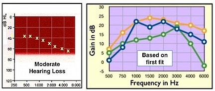
Figure 1. Moderate sloping hearing loss (left) to which three premium RIC open-fit hearing aids were programmed. The frequency responses on the right are the 2cc coupler responses for the quick fit as prescribed by the manufacturers’ fitting software.
Earmold Coupling – the Key to a Successful RIC Fitting?
In the “old” days, especially when earmold modifications were regularly employed to fit BTE (behind-the-ear) hearing aids (before RICs), user success was often better achieved with an “acoustical” modification to the earmold that changed the response rather than an “electronic” response change.
Effect of Acoustic Frequency Response on RIC Hearing Aids
Background
It is a fact that the type of “earmold” or coupling of the hearing aid to the ear changes the 2cc coupler response of the hearing aid when fitted to the ear. The ANSI Standard 2cc coupler has a volume too large to represent a normal ear, but is acknowledged instead as a universal method for an inter-comparison of the electroacoustic performance of hearing aids.
The measured 2cc response has little to do with the actual hearing aid fitting. Ear canals are generally less than the 2cc volume – closer to 1.2cc and sometimes as little as 0.5cc, especially with some RIC instruments. Small ear canals (more common in women and children, but not limited to them) have a reduced residual volume between the tip of the earpiece and the tympanic membrane. As a result, they are subjected to greater overall sound pressure levels, meaning that they do not require as much gain as a hearing aid fitting formula might recommend. Large ear canals, on the other hand, have larger volumes, and, as a result, require greater gains that may be closer to those recommended by a hearing aid fitting formula (which is based on a 2cc volume and a sensorineural hearing loss) – Boyle’s Law. Additionally, some frequency response changes occur as well, related to the residual volume, depending on whether or not the tip is sealed in the ear canal.
As mentioned above, experience suggests that a patient may prefer hearing aid amplification where the response has been adjusted acoustically (using earmold modification approaches), rather than electronically. Attempts to fit a high-frequency hearing loss with an electronically generated high-frequency emphasis hearing aid is generally a prescription for disaster. Not only does this lead to consumer dissatisfaction with the “tinny/sharp” sound, but also to acoustic feedback–a problem that has haunted hearing aid fittings ever since they first attempted to provide substantial high-frequency gain. This general “mirroring of the audiogram” approach has helped spur design engineers to develop sophisticated feedback-reduction circuitry, and manufacturers to develop proprietary fitting formulae often based on satisfying the complaints of consumers who have returned their instruments for credit.
Acoustic Fitting Information
Can hearing aid performance be modified sufficiently acoustically to satisfy intended amplification needs to meet user acceptance and satisfaction? Using a RIC hearing aid programmed for an open fit based on the audiogram in Figure 1, the range of earmold/fitting tips used with one instrument (green line recommended response from the computer program) is shown to provide substantial performance change (Figure 2). The recommended response as shown when measured in the 2cc coupler is not unique to this instrument. This response is reasonably typical of a sampling of RIC products from different manufacturers.
Frequency response variations in Figure 2 represent the effects of earmold (acoustic) changes from the 2cc programmed response (green curve). The key to the right of the graph identifies the RIC tips measured to record these results. The green line represents the 2cc closed coupler response of the recommended hearing aid. The remainder of the responses were obtained measured into an open coupler (Frye Electronics) using the vented tips identified.
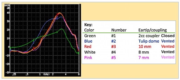
Figure 2. Frequency response changes resulting from changing the tips of RIC hearing aids. The green line represents the 2cc coupler response recommended for the audiogram levels of Figure 1. The other colored lines are identified in the key to the right, and were all measured into an open coupler.
Measurement Method
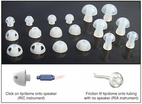
The hearing aid frequency response changes dramatically when the earmold/fitting tip is altered. Other than the 2cc coupler measurement (green curve), all other responses were recorded using a Frye Electronics Open Coupler (Figure 3A). The fitting tips were all vented to some degree and provided as off-the-shelf tips.
The Frye coupler was developed for open mold fittings. It has a diameter of 9mm, which is close to the average ear canal diameter, and the entry tube of the coupler was designed to provide an ear canal resonance close to that of a real ear. A damping element has been added to reduce the high resonance peak to make it closer to what a hearing aid will produce in the real ear. The entry tube continues straight back to, and is terminated by, a pressure measuring microphone. The dome/tip of the RIC receiver/speaker fits into the opening of the coupler, just as it would insert into the patient’s ear (Figures 3B, 3C, and 3D). No other sealing is necessary. Previous measurements show this coupler to have similar responses to open fitting as when measured with real-ear. (Note: No Standard exists for an open coupler).
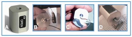
Figure 3. Open coupler (A) used for RIC tip measurements (Frye Electronics). B shows the RIC tip at the entrance of the 9mm diameter “canal” opening into the coupler prior to insertion. C shows the tip and speaker into the open coupler, and D shows how the speaker/receiver and tip fit into the coupler for measurement when seen from the side.
Reviewing the open coupler responses in Figure 2 provides evidence that substantial high-frequency amplification occurs – and perhaps way too much high-frequency emphasis resulting from the vents/leakage in the ear tip. Too much high-frequency emphasis often results in a hearing aid sounding “scratchy, distorted, shrill, etc.” To solve this fitting problem, dispensers modify the electronic programmed frequency response, undoubtedly employing substantial feedback reduction, in order for this fitting to be acceptable to the user.
It is unclear to what extent any acoustic modification effect is compensated for by hearing aid manufacturing programming software. If not managed in the software, resolving the problem becomes the responsibility of the hearing aid dispenser. And, without real-ear, guesswork and patient comments are the order of the day.
Note: Equipment for making these measurements was made available by Frye Electronics.
Next week’s post will continue this discussion by explaining how knowing more about earmold modifications can be useful, especially with fitting problem cases.